I’m sorry to hear that, been there too. ![]()
I really like it’s front-page ![]() GitHub - cbruiz/printhor: A 3dprinter/cnc firmware framework powered by rust embassy
GitHub - cbruiz/printhor: A 3dprinter/cnc firmware framework powered by rust embassy
I’m sorry to hear that, been there too. ![]()
I really like it’s front-page ![]() GitHub - cbruiz/printhor: A 3dprinter/cnc firmware framework powered by rust embassy
GitHub - cbruiz/printhor: A 3dprinter/cnc firmware framework powered by rust embassy
Yeah, I have this little dream of a 2x2 linear motor 3d printer running on rust. I’m in the process of putting together the rust equivilent of sfoc at the moment, hoping that’s used.
What exactly do you mean by 2x2? I hate Rust, so we could only collaborate on hardware, but I have a dream of a printer using the Ultimaker style crossed rail gantry with two linear motors driving each axis. Ideally inverted from the Peopoly Magneto X, so the permanent magnets are on the moving parts and coils on the stationary rails so the motor wires don’t have to move. This is one of the potential uses for my stepstick-compatible board, along with making ultra-lightweight spiral extruders.
I’m pretty sure I could make the linear motors, but I don’t know what to do about encoders. It seems stupid to use belts to turn rotary encoders, but I don’t know of any low-cost linear encoders aside from vernier calipers, which may not be precise enough even if you can figure out how to get the reading from them in digital format.
check out the diy linear motor project: GitHub - cmore839/DIY-Linear-Motor.
The project owner has the same setup in mind as you regarding placement: Cross gantry, 2 lin-mot per axis.
As for inverting the coils/magnets, that’s a thinker. It would significantly inclease the moving mass, and you wold need a way to set which phase triplets to activate. You wouldn’t have enough default gpio-pins available, so you would probably need a multiplexer of some sort. I could see heat disapation being a massive advantage, assuming you can share the coil-energisiation across more than just 6 coils, but the wire advantage, I don’t see as being much of an advantage. With reasonable cable management, it should be a near non-issue. I would be keen to hear your thinking on it.
Making linear motors, as per the DIY linear motor I linked, seems quite straight forward, they’ve even got a coil supply setup if that part of the project doesn’t appeal. As for encoding, there’s linear encoder options:
The rotary encoders are probably more than suitable for prototyping, at least.
I hate Rust
I love the language for a lot of reasons. I love klipper, but the project owner is, in my experience, and it seems quite common among those that I’ve spoken with, is driven by ego, and filters the community such that he is surrounded by sycophants. The community and industry deserve better, and if something else comes along, I feel that it deserves to be in a modern language.
Ah, that looks more realistic than what I had in mind. The rails would be like an unrolled outrunner stator, with coils wound around teeth. The moving part would be two rectangle magnets stuck to a piece of iron, so moving mass would be extremely low. It’s true that wires and cable chain aren’t that heavy, but it lacks the elegance of my pie-in-the-sky machine ![]()
Thanks for the encoder recommendations, but I forgot the main reason it’s such a problem is that it also needs to be inverted so the sensors are on the rails, else the carriage will still have to drag wires around. That will have the advantage of giving an absolute position reading, but I doubt there are any commercially available solutions for it. I feel like the answer will involve a vernier pattern, using capacitance, magnetic field, light, or electrical contact.
Regarding selectively activating coils, I had considered it but I don’t think it’s really necessary. It will be producing a lot of unnecessary magnetic field, but since nothing will be pushing against it the only energy consumption should be in the resistance of the copper wire, and since that won’t be moving you can use a lot of it to minimize resistance. Although cost could be an issue.
Something I recently have been looking into is trying to replicate and improve the work on this project, which does not have fantastic resolution but depending on your number of pole pairs, could possibly work : Project | DIY Digital Caliper - CALIPATRON | Hackaday.io
Magnificent! I found about it last week, I really want it to move forward.
The only thing about capacitive encoders that I’m not too sure about is their sampling rate, and if they are any good measuring while in (“fast”) motion.
There is also the cheap-o-self-mixing laser interferometer: https://www.youtube.com/watch?v=MUdro-6u2Zg
There is also optical strips and magnetic tape for linear encoders:
I’m just starting to explore these options for a stick-slip piezoelectric nanopositioner (i.e. not recommending those products or suppliers).
Haha! We are living the same life on two separate halves of the planet… I have been obsessed with trying to build a << 1um resolution encoder for use with a nanopositioner also… I watched this video and the Sam Zeloof one recently. I think they are actually maybe too impractical for the stage you/me are talking about.
At my work we use the optical tape with very high pitch for closed loop motor control, but even this tape is like $100 per inch or soomething like that.
Did you read the paper in HardwareX also? I just ordered the parts to try and build it, I think that using some of those 28-bit inductive sensors might be the best method to set up a closed loop. I will dm you ![]()
Interesting, can I ask for a link to the specs?
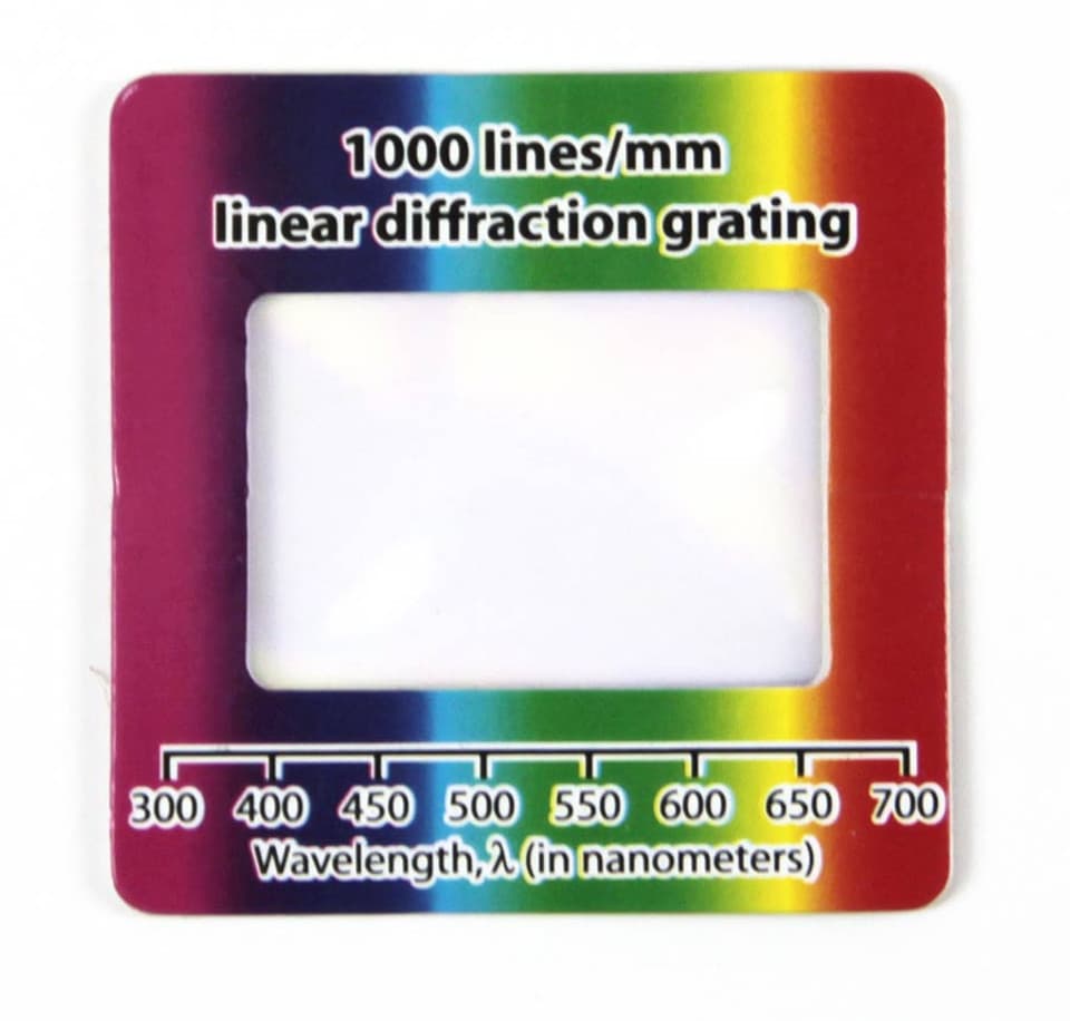
I was thinking about using this kind of things as “optical tape”:
Or these:
Would they be useful?
I’m also not sure what sensor can be used to read from them. I imagine that either a very fine laser point (like the ones in OPUs) could work, or maybe the sensor from a high-DPI computer mouse (e.g. this thesis).
Hoping the rough ideas are useful. Implementation is out of my reach ATM.
FYI Magnetic encoders from RLS can get to 250nm/count for around $100/ea for tape and readhead, this is the cheapest “high” resolution encoder I know of from a non-ali type source.
I laid out an adapter board for a nucleo-144 that connects 4x ali drv8301 driver boards, and has SE/differential encoder inputs, along with some SPI/UART/gpio broken out to connectors. It’s laid out around the H723 peripherals, but I think nucleos are designed to be pretty interchangeable so hopefully the F7 and U5 I also have will at least partly work.
I’m back with ideas.
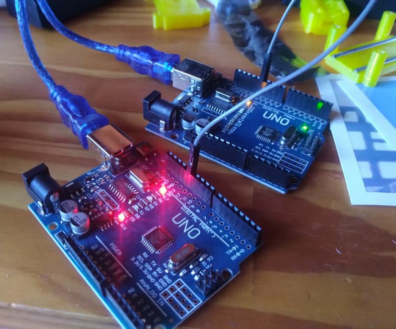
Just found about PJON, and got totally carried away: GitHub - gioblu/PJON: PJON (Padded Jittering Operative Network) is an experimental, arduino-compatible, multi-master, multi-media network protocol.
After jumping around for a bit, it was working (as per https://youtu.be/8okhWVkMnng?si=oOIyIi07I1_sTOd2&t=371).
With the following results:
---------------------
Packet Overhead: 10B - Total: 640B
Bandwidth: 1920B/s
Data throughput: 1280B/s
Packets sent: 64
Fail (no acknowledge from receiver): 0
Busy (Channel is busy or affected by interference): 0
Delivery success rate: 100.00 %
Avg. round-trip ACK latency: 15.685 ms
Latency standard deviation: 0.008 ms
---------------------
I wonder if this protocol could be enough to keep the clocks of the MCUs in the network in sync, and play along with everything else I need the MCUs to do.
I can’t say I understand the limitations in PJON relative to CAN, but this looks promising when thinking about daisy chaining 3 arduinos to drive 3 motors with SimpleFOC.
Look mum one wire!The basic idea here is to get one “planning MCU”[1] to accept GCODE, do the time-stamped planning, and let everyone else in the PJON network do stuff in sync.
I’m not sure about the speed of the link though, or how it will interact with the time-sensitive SimpleFOC code.
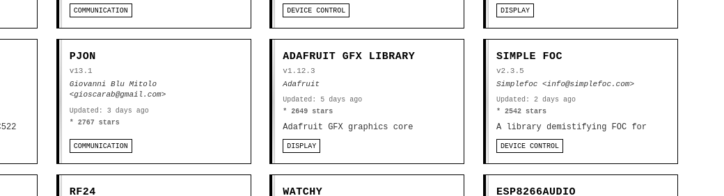
Possible names for this include PjonFOC. It is meant to be, if only adafruit GFX were not in the way.
I mainly wanted to share. Cheers to everyone!
That planning MCU can instead be a PC or Raspberry Pi, running python-pjon. Just like in klipper’s klippy. ↩︎
Don’t know about you, but i find this jaw dropping:

Has it ever been easier for commoners like me to achieve this? I’m thrilled
Well, tests reveal that SFOC’s interrupts mess with PJON’s bitbang, and viceversa. Incompatibility is the name of the play.
There is a non-blocking I2C library I’m interested in trying out: GitHub - nitacku/nI2C: A non-blocking I2C library for Arduino/AVR without limitations!
See you in another 12 months (?)
My current project of closing the loop on my CNC stepper motors is going to need non-blocking I2C communication, but I’ll probably just go with direct hardware register access. ATMega’s TWI registers are easy to work with. I haven’t learned STM32’s yet, but since that library wouldn’t work with it, I’d have to go looking for a different one anyway.
My plan is to have one Nano that runs GRBL, whose job is to process the data stream from the PC and output step/dir signals to the motor drivers (my Gooser5), and an Arduino Pro Mini whose job is to read some of the manual controls and send I2C commands to the drivers, and receive the motor positions from the drivers to display on a little OLED. The drivers will run in angle_nocascade mode since GRBL already handles generating acceleration ramps for them.
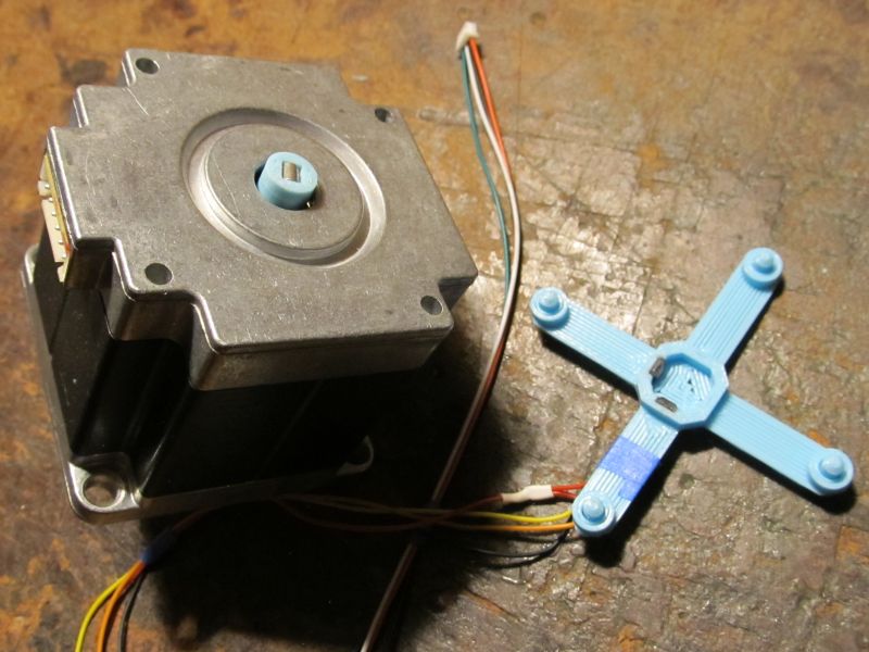
I’ve been working on some fun encoder code, using two 49E linear hall sensors and a 3x4mm cylindrical magnet on the motor shaft.
#ifndef SIN_COS_ENCODER_H
#define SIN_COS_ENCODER_H

// This function can be overridden with custom ADC code on platforms with poor analogRead performance.
__attribute__((weak)) void ReadSinCosEncoder(int pinA, int pinB, uint16_t *a, uint16_t *b)
{
  *a = analogRead(pinA);
  *b = analogRead(pinB);
}

class SinCosEncoder: public Sensor {
  public:
    SinCosEncoder(int _pinA, int _pinB) : pinA(_pinA), pinB(_pinB) {}

    void init(uint16_t _minA, uint16_t _maxA, uint16_t _minB, uint16_t _maxB,
      uint16_t _centerA, uint16_t _centerB, uint16_t _thirtyA, uint16_t _sixtyA, int _lut_resolution,
      const uint16_t *_lutAP, const uint16_t *_lutAN, const uint16_t *_lutBP, const uint16_t *_lutBN)
    {
      minA = _minA; maxA = _maxA; minB = _minB; maxB = _maxB;
      centerA = _centerA; centerB = _centerB; thirtyA = _thirtyA; sixtyA = _sixtyA;
      lut_resolution = _lut_resolution;
      lutAP = _lutAP; lutAN = _lutAN; lutBP = _lutBP; lutBN = _lutBN;
    }

    // Perform full calibration. The tables passed in here will be filled with data and their pointers retained.
    void init(FOCMotor *motor, int calibration_steps, int _lut_resolution,
      uint16_t *_lutAP, uint16_t *_lutAN, uint16_t *_lutBP, uint16_t *_lutBN)
    {
      int i, j;
      uint16_t a, b;
      int32_t tableA[calibration_steps+1]={0}, tableB[calibration_steps+1]={0}; // Extra entry at the end to simplify interpolation code

      lut_resolution = _lut_resolution; lutAP = _lutAP; lutAN = _lutAN; lutBP = _lutBP; lutBN = _lutBN;

      Serial.println("SinCosEncoder: Begin calibration movement");
      // Rotate motor forward and back, recording the sensor values at each step.

      // Move slightly negative, so first loop iteration moves forward like subsequent iterations
      motor->setPhaseVoltage(motor->voltage_sensor_align, 0, _electricalAngle(-1 * _2PI / calibration_steps, motor->pole_pairs));
      delay(2000 / calibration_steps);
      for (j = 0; j < 4; j++)
        for (i = 0; i < calibration_steps; i++) {
          uint32_t time = 2000000 / calibration_steps, start_time = _micros();
          while(_micros() < start_time + time) {
            float a = (i - 1) + (float)(_micros() - start_time) / time;
            motor->setPhaseVoltage(motor->voltage_sensor_align, 0, _electricalAngle(a * _2PI / calibration_steps, motor->pole_pairs));
          }
          ReadSinCosEncoder(pinA, pinB, &a, &b);
          tableA[i] += a;
          tableB[i] += b;
        }
      // Complete previous revolution, so first loop iteration moves backward like subsequent iterations
      motor->setPhaseVoltage(motor->voltage_sensor_align, 0, 0);
      delay(2000 / calibration_steps);
      for (j = 0; j < 4; j++)
        for (i = calibration_steps - 1; i >= 0; i--) {
          uint32_t time = 2000000 / calibration_steps, start_time = _micros();
          while(_micros() < start_time + time) {
            float a = (i + 1) - (float)(_micros() - start_time) / time;
            motor->setPhaseVoltage(motor->voltage_sensor_align, 0, _electricalAngle(a * _2PI / calibration_steps, motor->pole_pairs));
          }
          ReadSinCosEncoder(pinA, pinB, &a, &b);
          tableA[i] += a;
          tableB[i] += b;
        }

      for (i = 0; i < calibration_steps; i++)
        tableA[i] >>= 3, tableB[i] >>= 3;
      // Set extra entry at end of tables, used for interpolation
      tableA[calibration_steps] = tableA[0], tableB[calibration_steps] = tableB[0];

      //Serial.print("const uint16_t tableA[] = {");
      //printTable((uint16_t*)tableA, calibration_steps, true);
      //Serial.print("\n};\n\nconst uint16_t tableB[] = {");
      //printTable((uint16_t*)tableB, calibration_steps, true);
      //Serial.print("\n};\n\nconst uint16_t tableC[] = {");

      // Find min/max values, and their locations in the table (=the associated shaft angle)
      int minA_idx, maxA_idx, minB_idx, maxB_idx;
      minA = 65535, maxA = 0, minB = 65535, maxB = 0;
      for (i = 0; i < calibration_steps; i++) {
        if(tableA[i] <= minA) minA = tableA[i], minA_idx = i;
        if(tableA[i] >= maxA) maxA = tableA[i], maxA_idx = i;
        if(tableB[i] <= minB) minB = tableB[i], minB_idx = i;
        if(tableB[i] >= maxB) maxB = tableB[i], maxB_idx = i;
      }

      // Center value is 90 degrees from min and max, not simply the average of min and max since
      // axial magnet offset will cause one to be farther from center than the other.
      // Use average going both directions from min and max to improve accuracy even further.
      centerA = (uint16_t)(((uint32_t)
        tableA[(minA_idx + calibration_steps/4) % calibration_steps] +
        tableA[(maxA_idx + calibration_steps/4) % calibration_steps] +
        tableA[(minA_idx + calibration_steps*3/4) % calibration_steps] +
        tableA[(maxA_idx + calibration_steps*3/4) % calibration_steps]) / 4);
      centerB = (uint16_t)(((uint32_t)
        tableB[(minB_idx + calibration_steps/4) % calibration_steps] +
        tableB[(maxB_idx + calibration_steps/4) % calibration_steps] +
        tableB[(minB_idx + calibration_steps*3/4) % calibration_steps] +
        tableB[(maxB_idx + calibration_steps*3/4) % calibration_steps]) / 4);

      // The revolution is divided up into 8 sectors. In the four sectors where one sensor is near its sine wave peak,
      // only the other sensor is used. In the other four sectors, the output angle is a weighted combination of the
      // value from each sensor, so there's no discontinuity at the sector boundaries.
      // The blended sectors each span 30 degrees, while the single-sensor sectors each span 60 degrees.
      // Only sensor A is used to determine the sector boundary locations, which don't need to be exact. Else I would
      // use a similar averaging process as the center values above.
      thirtyA = tableA[(minA_idx + calibration_steps*4/12) % calibration_steps];
      sixtyA = tableA[(minA_idx + calibration_steps*5/12) % calibration_steps];

      Serial.println("SinCosEncoder: Generating lookup tables");

      // Generate lookup tables to convert raw ADC data to shaft angle.
      // Note: It's possible some entries near the peaks will not be filled, but that's ok since they'll never be used anyway.
      // It would be possible to save a bit of space by not storing those entries at all, but more trouble than it's worth.
      for (i = 0; i < lut_resolution; i++) {
        a = minA + (uint32_t)(maxA - minA) * i / lut_resolution;
        b = minB + (uint32_t)(maxB - minB) * i / lut_resolution;
        // Reverse interpolated lookup to find the shaft angles that go with these sensor values
        for (j = 0; j < calibration_steps; j++) {
          if((tableA[j] <= a && tableA[j + 1] >= a) || (tableA[j + 1] <= a && tableA[j] >= a)) {
            int32_t val = ((int32_t)j + calibration_steps - minA_idx) << 16; // Integer portion of shaft position for this sensor value
            val += (((int32_t)a - tableA[j]) << 16) / (tableA[j + 1] - tableA[j]); // Fractional portion
            val /= calibration_steps; // Range is now 0-65535 for one revolution
            (tableB[j] < centerB) ? (_lutAN[i] = (uint16_t)val) : (_lutAP[i] = (uint16_t)val);
          }

          if((tableB[j] <= b && tableB[j + 1] >= b) || (tableB[j + 1] <= b && tableB[j] >= b)) {
            int32_t val = ((int32_t)j + calibration_steps - minA_idx) << 16;
            val += (((int32_t)b - tableB[j]) << 16) / (tableB[j + 1] - tableB[j]);
            val /= calibration_steps;
            (tableA[j] < centerA) ? (_lutBN[i] = (uint16_t)val) : (_lutBP[i] = (uint16_t)val);
          }
        }
      }
      Serial.println("SinCosEncoder: Calibration complete");
      printCalibration();
    }

    // Helper function to look up shaft angle corresponding to sensor value
    uint16_t InterpolatedLookup(const uint16_t *lut, uint16_t val, uint16_t range) const {
      int idx = (uint32_t)val * lut_resolution / range;
      int frac = (uint32_t)val * lut_resolution % range;
      return (uint16_t)((int32_t)lut[idx] + ((int32_t)((int16_t)(lut[idx+1] - lut[idx])) * frac / range));
    }

    float getSensorAngle() override {
      uint16_t a, b;
      ReadSinCosEncoder(pinA, pinB, &a, &b);
      lastA = a;
      lastB = b;

      if(a >= sixtyA || a <= centerA - (sixtyA - centerA)) { // A is near peak. Use B reading only.
        angleA = blended = 0;
        angleB = InterpolatedLookup(a < centerA ? lutBN : lutBP, b - minB, maxB - minB);
        return (float)angleB * (_2PI/65536.0f);
      }
      else if(a <= thirtyA && a >= centerA - (thirtyA - centerA)) { // A is near center, therefore B is near peak. Use A only.
        angleB = blended = 0;
        angleA = InterpolatedLookup(b < centerB ? lutAN : lutAP, a - minA, maxA - minA);
        return (float)angleA * (_2PI/65536.0f);
      }

      // Otherwise both sensors have good data. Fade from one to the other so there are no
      // discontinuities at the sector boundaries.

      // Convert sensor readings to angle depending on quadrant. In a perfect world, both angles would be equal.
      angleA = InterpolatedLookup(b < centerB ? lutAN : lutAP, a - minA, maxA - minA);
      angleB = InterpolatedLookup(a < centerA ? lutBN : lutBP, b - minB, maxB - minB);

      // Alpha goes from 0 to 1<<8 as a goes from thirtyA to sixtyA, above or below centerA
      int32_t alpha = ((int32_t)(abs((int16_t)(a - centerA)) - (int16_t)(thirtyA - centerA)) << 8) / (sixtyA - thirtyA);
      blended = (uint16_t)(angleA + (alpha * (int16_t)(angleB - angleA) >> 8));
      return (float)blended * (_2PI/65536.0f);
    }

    static void printTable(const uint16_t *table, int num, bool is32bit = false) {
      for (int i = 0; i < num; i++) {
        if(!(i & 7)) { Serial.print("\n\t"); delayMicroseconds(200); }
        if(is32bit) Serial.print(((uint32_t*)table)[i]); else Serial.print(table[i]); delayMicroseconds(200);
        if(i != num - 1) { Serial.print(", "); delayMicroseconds(200); }
      }
    }

    // Print data to serial so it can be copy/pasted into the code to avoid re-calibrating every startup.
    void printCalibration() const {
      Serial.print("\tsensor.init("); delayMicroseconds(200);
      Serial.print(minA); Serial.print(", "); delayMicroseconds(200);
      Serial.print(maxA); Serial.print(", "); delayMicroseconds(200);
      Serial.print(minB); Serial.print(", "); delayMicroseconds(200);
      Serial.print(maxB); Serial.print(",\n\t\t"); delayMicroseconds(200);
      Serial.print(centerA); Serial.print(", "); delayMicroseconds(200);
      Serial.print(centerB); Serial.print(", "); delayMicroseconds(200);
      Serial.print(thirtyA); Serial.print(", "); delayMicroseconds(200);
      Serial.print(sixtyA); Serial.print(", "); delayMicroseconds(200);
      Serial.print(lut_resolution); delayMicroseconds(200);
      Serial.print(",\n\t\tlutAP, lutAN, lutBP, lutBN);\n\nconst uint16_t lutAP[] = {"); delayMicroseconds(200);
      printTable(lutAP, lut_resolution);
      Serial.print("\n};\n\nconst uint16_t lutAN[] = {"); delayMicroseconds(200);
      printTable(lutAN, lut_resolution);
      Serial.print("\n};\n\nconst uint16_t lutBP[] = {"); delayMicroseconds(200);
      printTable(lutBP, lut_resolution);
      Serial.print("\n};\n\nconst uint16_t lutBN[] = {"); delayMicroseconds(200);
      printTable(lutBN, lut_resolution);
      Serial.print("\n};\n"); delayMicroseconds(200);
   }

    int pinA, pinB; // CPU pin that each sensor is connected to
    uint16_t centerA=0, centerB=0; // Sensor reading when magnet is perpendicular to it
    uint16_t minA=0, maxA=0, minB=0, maxB=0; // Minimum and maximum readings from each sensor during calibration
    uint16_t thirtyA=0, sixtyA=0; // Value of sensor A when shaft is 30 and 60 degrees above center
    const uint16_t *lutAP=NULL, *lutAN=NULL, *lutBP=NULL, *lutBN=NULL; // Lookup tables to convert sensor reading to shaft angle. Use N when other sensor is less than its center value.
    int lut_resolution=0; // Total number of entries in each lookup table
    uint16_t lastA=0, lastB=0; // Last sensor readings, only retained for debugging purposes
    uint16_t angleA=0, angleB=0, blended=0; // Last angle values calculated for each sensor, only retained for debugging purposes
};

#endif
And the ADC setup:
// The ADC is set up to read 8 channels continuously, and this array stores the last kADCSamples readings for each of them.
// So elements 0,8,16,24... are the most recent readings of one ADC channel, elements 1,5,17,25... are the next channel, etc.
// It would be simpler to increase the hardware oversampling, but this way allows for spike filtering, and
// ensures that all channels' samples were taken over roughly the same span of time, versus some channels
// having all fairly recent samples and others having all fairly old samples.
const int kADCSamples = 16;
volatile u16 adcData[8*kADCSamples];

uint16_t getADCValue(int pin) {
  int i;
  int32_t val = 0;
  uint16_t samples[kADCSamples]; // Non-volatile copy of samples from adcData
  // Add up all the samples in the buffer
  for (i = 0; i < kADCSamples; i++)
    val += (samples[i] = adcData[pin+(i<<3)]);

  // Find which sample deviates most from the average, and remove it from the mix (spike filter)
  int32_t diff, worstDiff=0;
  int worstIdx=0;
  for (i = 0; i < kADCSamples; i++) {
    diff = abs((int32_t)samples[i] * kADCSamples - val);
    if(diff > worstDiff)
      worstDiff = diff, worstIdx = i;
  }
  val -= samples[worstIdx];
  return val / (kADCSamples-1);
}

float _readADCVoltageInline(const int pin, const void*)
  { return (3.3f/65536.0f) * getADCValue(pin); }
void* _configureADCInline(const void*, const int pinA, const int pinB, const int pinC)
  { return new Stm32CurrentSenseParams { .pins = { pinA, pinB, pinC }, .adc_voltage_conv = 3.3f/65536.0f }; }
void ReadSinCosEncoder(int pinA, int pinB, uint16_t *a, uint16_t *b)
  { *a = getADCValue(pinA), *b = getADCValue(pinB); }


void setup() {
  RCC->AHB1ENR |= RCC_AHB1ENR_DMAMUX1EN | RCC_AHB1ENR_DMA1EN;
  RCC->AHB2ENR |= RCC_AHB2ENR_ADC12EN;
  RCC->CCIPR |= RCC_CCIPR_ADC12SEL_1; // ADC use SYSCLK
  ADC1->CR &= ~ADC_CR_DEEPPWD; ADC2->CR &= ~ADC_CR_DEEPPWD;
  ADC1->CR |= ADC_CR_ADVREGEN; ADC2->CR |= ADC_CR_ADVREGEN;
  delayMicroseconds(20); // Regulator startup time from STM32G431CB datasheet
  // Dual mode regular simultaneous, circular DMA, DMA enable for 12-bit, clock 170MHz/4 = 42.5MHz
  ADC12_COMMON->CCR = 6 | ADC_CCR_DMACFG | ADC_CCR_MDMA_1 | ADC_CCR_PRESC_1;
  ADC1->CR |= ADC_CR_ADEN; ADC2->CR |= ADC_CR_ADEN;
  while(!(ADC1->ISR & ADC_ISR_ADRDY)){} // Wait for ADC startup
  ADC1->CFGR = ADC2->CFGR = ADC_CFGR_CONT | ADC_CFGR_OVRMOD; // Convert continuously, ignore overrun
  ADC1->CFGR2 = ADC2->CFGR2 = ADC_CFGR2_ROVSE | ADC_CFGR2_OVSR_1 | ADC_CFGR2_OVSR_0; // 16x oversampling
  DMAMUX1->CCR = 5; // ADC1, from Table 91 on page 420 of reference manual rm0440
  DMAMUX1_RequestGenerator0->RGCR = DMAMUX_RGxCR_GE;
  DMA1_Channel1->CNDTR = sizeof(adcData)/4;
  DMA1_Channel1->CPAR = (u32)&ADC12_COMMON->CDR;
  DMA1_Channel1->CMAR = (u32)&adcData;
  // 32-bit memory, 32-bit peripheral, increment dest address, circular mode, start DMA
  DMA1_Channel1->CCR = DMA_CCR_MSIZE_1 | DMA_CCR_PSIZE_1 | DMA_CCR_MINC | DMA_CCR_CIRC | DMA_CCR_EN;
  // Note: Actual number of conversions is 1 more than specified in SQR1 low bits.
  // Note: ADC1 and ADC2 can't convert the same channel number at the same time.
  // S0:A1C11,A12C14,A2C12  S1:A12C2,A12C1,A1C10  E0:A2C4,A1C4,A2C3  E1:A2C13,A1C3,A2C17  VBUS:A2C5
  #define ADCSQ(idx, ch) ((ch) << ((idx)*6)) // More concise than the ADC_SQRx_SQy #defines
  ADC1->SQR1 = 3 | ADCSQ(1,11) | ADCSQ(2,2) | ADCSQ(3,1) | ADCSQ(4,3); // S0A, S1A, S1B, E1B
  ADC2->SQR1 = 3 | ADCSQ(1,14) | ADCSQ(2,13) | ADCSQ(3,17) | ADCSQ(4,5); // S0B, E1A, E1C, VBUS
  ADC1->CR |= ADC_CR_ADSTART;
  delayMicroseconds(100); // Wait for first ADC conversions to complete
What is the I2C command sent to the drivers?
And why do you use two 49E linear hall sensor as the encoder, not use the AS5047 or MT6816 etc?
I think just spindle speed and the three stepper enable switches. I may end up wiring those controls directly to the drivers, so I2C is only used to report motor positions to the Pro Mini. There will also be 3 buttons for zeroing the positions for quick manual probing, but I think that will only affect the OLED display, so won’t need communicated to the drivers. It would be nice if I could communicate to the GRBL Nano and/or PC to ensure that the internal positions remain consistent with what’s shown on the OLED, but I don’t think it’s possible.
Because I’m poor and already had these sensors and magnets on hand. I figured I’d see if I can make it work before spending any more money and waiting for shipping. Now we can all have high precision for dirt cheap ![]()
Why don’t you use the bus such as CAN to connect all the device?
Hope to see your final test.
CAN needs an extra transceiver chip, and as far as I know the only reason to use it is when you need long wire runs in electrically noisy environments. My I2C lines will only be a few inches long, so I doubt there will be any noise issues.
That said, the popularity of CAN does make me feel compelled to add it to Gooser.
Does anyone have advice on doing precise angle control without the motor constantly vibrating at the target? I’m going to try adding a deadband zone where it won’t correct position errors below a certain threshold, but since SimpleFOC doesn’t have that built in, maybe there’s some other way I don’t know.
Plotting my angle reading in units of 1/6400 of a revolution (equivalent to 32x microstepping) I’m getting jitter of ±1, with occasional jumps to ±2.
To minimize the number of variables, I’m using pure voltage control (TorqueControlType::voltage without providing phase resistance and kv), which limits the top speed but gives instant and predictable response for position holding.
The best I’ve been able to get with PID is holding within about ±10 units when I twist on the shaft by hand, although it does get up to ±15 if I jiggle back and forth. Regular angle mode seems to be working better than angle_nocascade at the moment. Nocascade is more like ±20, and starts oscillating if I increase P above 150.
With cascaded velocity, I’m using angle P=20, velocity P=10 and I=100. The I value seems very large, but without it I can push it pretty far off target before it responds with enough torque to correct it. Angle P=50 holds within ±5 units, but overshoots when moving to a target.
EDIT: For some reason, nocascade mode works well with Angle_P.I set to obscenely large values. It overshoots by about 15 units when moving to a target, but that may not be an issue when following small changes from step/dir. And the higher the I value, the faster the overshoot is corrected, and more accurate the holding. With Angle_P.P=100, Angle_P.I=5000 holds within ±5 units. With I=50000, it holds within ±2 units, and overshoot is corrected in less than 50ms since it doesn’t show up on my printout most of the time.
I also tried using D in regular angle mode and nocascade, but as always it just causes buzzing and worse tracking.