Can I commutate a 3-phase brushless motor with 1x L298N?

Hey SimpleFOC community!

I’ve been trying to implement some basic commutation from scratch (as a learning exercise) using a L298N and a small 3 phase brushless motor. I’m a little confused as to whether it is possible to get commutation working properly with a single L298N. In the meantime, I am just using two L298Ns… but this is nagging at me!

So, I am assuming that I want to be able to energize the phases such that I can have current flowing from:

  1. phase W → phase V
  2. phase W → phase U
  3. phase V → phase W
  4. phase V → phase U
  5. phase U → phase W
  6. phase U → phase V

Looking at the block diagram of the L298N, I’m not sure that this is possible. Below is the block diagram of the L298N, and I’ve draw a 3-phase motor and have connected the W, V and U phases to OUT1, OUT2 and OUT3 respectively:

Below I have a table with the desired sequence of phase connections to ground, power supply (Vs) and not connected (NC). I am trying to figure out how to set the pins of the L298N to go through this sequence (i.e. fill out all the "?"s).

unfilled_commutation_table

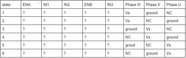
So here is what I might try to get through the sequence, though I left a few of the cells as “?” to highlight my question.

filled_commutation

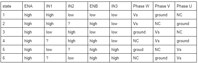
So state 1 and state 3 are simple enough. In state 1, current flows from Phase W to Phase V, and in state 3, current flows from Phase V to Phase W. The issue is with states 2, 4, 5 and 6.
Let’s take state 2 for example. I want the current to flow from Phase W to Phase U. So I set the ENA-high, and I set the IN1-high which connects Phase W to power supply (Vs). And I set ENB-high and IN3-low, which connects Phase U to ground. But now, what do I do with Phase V?! I can’t set ENA-low to make it NC because that would disable IN1 and IN2. If I set IN2-high, then Phase W and Phase V are connected to power supply, so current flows from Phases W & V to Phase U. If I set IN2-low, then Phase V is connected to ground, and current flows from Phase W to phases U and V.
I come across his same issue for states 4, 5, and 6.

So this leads me to think that it is not possible to do this type of commutation with a single L298N. Am I crazy? Am I missing something? For the example I went through - state 2 - could I just PWM IN2 at 50% duty cycle such that it is fluctuating being connected between ground & voltage supply and hope that motor inductance prevents any current flow?

Curious to hear any thoughts!

Hi,

[Edit]

For many of the DC motor drivers the half-bridges can’t be controlled independently… but on the L298N they can.

The circuit diagram you posted actually contains the information you’re looking for, its also like a “logic diagram”.

Each half-bridge is controlled by an IN signal and the (shared) EN signal.
IN is inverted for the low-side transistor, and is ANDed with EN for both low side and high side. So you get:

ENA IN1 IN2 OUT1 OUT2
0 X X NC NC
1 0 0 0 0
1 0 1 0 1
1 1 0 1 0
1 1 1 1 1

So you should be able to connect a BLDC to one L298N driver, using 3 of its half-bridges…

See this thread also: 3$ BLDC and Stepper FOC driver - L298N

Thanks for the response @runger!

Is that true? I must not be understanding something because looking at the logic diagram (thanks for the heads up on the name for this diagram!), it would seem like they are explicitly not independent because they share the EN pin. This means that I cannot set the left half-bridge to NC, while the right half-bridge is connected to Vs or GND, right?

I’m maybe not following your table completely, I would think that on row 1 , OUT1 and OUT2 should be “NC” instead of “0” (does OUT1-0 mean GND and OUT1-1 mean Vs?). Also I think your table highlights my question, which is that the states of OUT1 and OUT2 are always 0 (GND?) or 1 (Vs?), and there is no way to make one half bridge “NC” (e.g. OUT1-NC) independently of the other half-bridge, because they share the EN.

Thanks for linking the thread! I dug through that a while back and thats actually what made me think it was possible to use a single L298N, but I didn’t find any convincing evidence in that thread… hence this thread!

Yes, you are right.

Yes, this is true and I have updated the table above to not confuse the next person reading this thread.

This is true. But this configuration is only needed for certain features like coasting, regeneration or if you wanted to do BEMF based control.
The “normal” SimpleFOC code doesn’t use the High-Z states.

The L298N, to be honest, has other shortcomings as BLDC driver, foremost its slow switching times. So it can’t really be recommended anyway, except for the price :wink:

Ahh interesting… I’m not familiar with the implementation of coasting, regen & BEMF. Can you explain (or provide a link) what you mean by High-Z states? High impedane meaning high & low-side mosfets of a half-bridge are OFF?

My experience in working with brushless motors & triple half-bridges is along the lines of the diagram below.

Point taken! I had L298Ns floating around and figured I’d use them… seems like its time to get some modern drivers :slight_smile:

Exactly that!

This is 6-step commutation, and indeed you need one phase in High-Z (off) state for it. But closed-loop field oriented control is much better than this in terms of efficiency/torque.

You could try it - in some applications it will work quite ok… you have to switch the PWM frequency down (to 5kHz or less) to stop it developing too much heat. It might be worth testing it out, but if you find it hard to achieve the speeds you need, or otherwise get bad performance its probably better not to spend too much time on it.

Ahh I see, I assumed a High-Z would also be required for FOC.

I’m just trying to learn the basics of different commutation methods, not looking for performance, so these should probably be ok.

Thanks for all the help!

I was not able to find a good solution for 3 or ideally 6 pin pwm power stages on their own. I resorted to some 5A capable darlington transistors, there is a pack that contains 4 pnp and 4 npn type ones on amazon. I don’t know how well this can work, but it seems like if you use an inverting buffer to drive one of them you should be able to get fast switching times and enough current and the truth table that you need. don’t forget clamping diodes? That may not be necessary, but I think it probably is.

@Anthony_Douglas. Sorry just getting around to your response. Are you saying that you weren’t able to find any good off-the-shelf triple h-bridge drivers, and just ended up making your own? I was just considering if it made sense to do this as well… The SimpleFOC Shields have all three half-bridge enable pins connected together, so I don’t think I can use those for my purposes (unless I start scratching out traces)

I think the package for this driver is pretty large, you can just lift the pins from the pad and then put your own wires on there (easier than scratching traces, which might not even be possible based on layout). But if you are just interested in learning basic commutation, why not just get some standalone MOSFET and breadboard something together?
Darlington configuration is also probably not great because they are based on this dual BJT design. At some frequencies you can get a phase inversion between the two BJT, and at others, bandwidth limited due to the frequency response, so you are limited in PWM frequency (additionally so by this old driver chip). It might be more educational to just make your own triple half bridge with discrete mosfets.

Many users here are making their own boards, for various different reasons…

But there are boards available (for example on AliExpress) which have separate EN inputs, or work in 6-PWM mode.
So its not strictly necessary to make your own board, but I think many people do it “for fun” :slight_smile: , and others do it because they want specific PCB shapes, specific functions or higher power levels…

1 Like

Yeah you are right, that would be the more reasonable route.

It’s seemin like that is the way to go. This project was meant to be a “learning C++” and “learning commutation” exercise, and not a “building circuits” exercise. But building a triple-half bridge appears to be the path of least resistance at this point

It’s really not. Unless your time is worth nothing, even a $200 eval board will be cheaper than building something yourself. There are plenty of boards on AliExpress for <$50, and many on digikey/mouser in the $50-$200 range.

Search on AliExpress for “SimpleFOC” and on Digikey/Mouser for things like BOOSTXL, or STSPIN.

But, on the other hand, building your own can be a very interesting and rewarding experience :slight_smile:

Ahh thanks for the reminder. Forgot about these. I’m taking a look at the B-G431B-ESC1 and some Nucleo hat options.