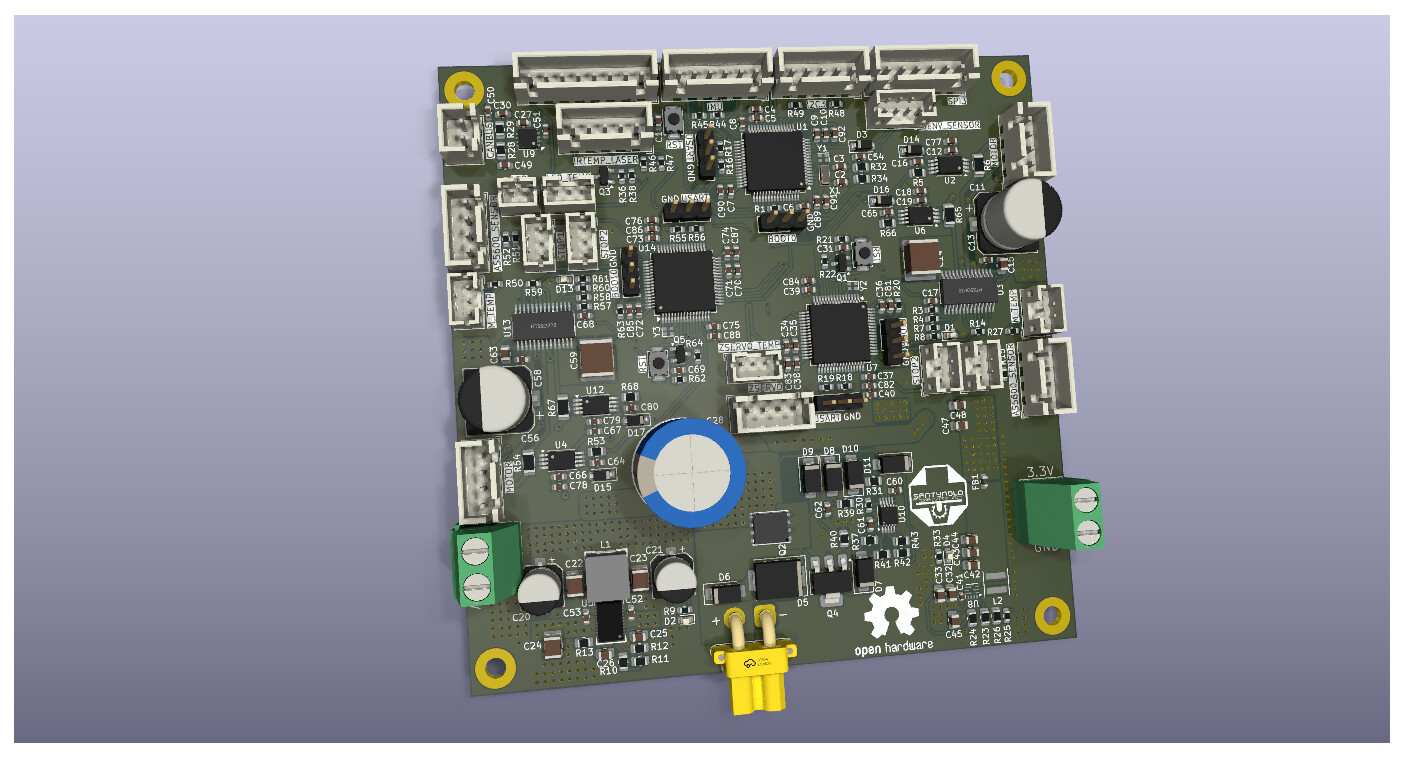
Hello everyone, i’m working on a custom PCB that implements FOC control for two NEMA17 stepper motors, with current sense and angle sensors. It actually does more stuff (that’s why it’s a mainboard) but thats not important for now.
My design (see below) uses 3x STM32G431 MCU’s. 1 “main” MCU, and two “Motor Control” MCU’s running simpleFOC.
My problem is that, checking PCBA prices, this board would cost upwards of 150 dollars, i’m just a highschool student, so i have to redesign.
My current setup uses AS5600 sensors (not in the design, i break out JST-XH I2C connectors for them, i cannot get breakout boards for other sensors). I was thinking, that maybe, since all of my MCU’s are already running at 168MHz with external clocks, i could remove one of them and save on components, and control two motors with one MCU, using SPI to communicate with the main MCU. Here are other constraints i have:
I cannot get breakout boards for other angle sensors locally. Only AS5600 (i would have to import them, not a problem, but i would like to avoid if possible)
Board should be compact, max 100x100mm (Already at the limit, it’s because of Economic PCBA constraints)
I am using INA240 current sense, and DRV8844 drivers.
I’m asking if this is a good idea, running two motors in one MCU (168MHz). Ideally with a good loop frequency. Also for angle sensor (AS5600) suggestions if this one doesn’t work for my application… Also also, this PCB controls a three axis manipulator, i almost forgot. That’s why a good loop frequency is required, right?
Thanks for your time and patience. Greetings from Argentina. Please ask if more info needed.
This looks like a sophisticated design, are all high school students in Argentina as advanced as you? It looks like very nice work!
Here are some comments for you:
controlling steppers with FOC is quite demanding on the MCU power, because steppers have a very high pole count (50 or 100 poles typically)
So running 2 steppers on one MCU will require some special care. It would be good to use high resolution ABZ based sensors which you can interface with low latency and zero overhead using the MCU timers in encoder mode. But such sensors like the MT6835 tend to cost a bit more.
The STM32G431 MCU costs $2-3 at LCSC, even with supporting components you’ll only save $10 or less by removing it
Don’t use the AS5600 for stepper control. It is too slow with I2C interface, and its accuracy is too low.
What connectors are you using? Is it all JST-XH? Are these original JST parts? If so then find some clone parts, you will save 90% of the costs, and since you have quite a lot of connectors that will add up to a few $
In fact, if you don’t mind sharing your schematics/BOM here then people might find some other ways to cheapen your design
What’s your concept for programming the three MCUs?
I’m sorry but for stepper motors this sensor is really not suitable. Even if you manage to get it working, performance will be terrible.
PWM mode is supported, but I encourage everyone to not use it. If used then it can work with low pole count BLDCs, and have terrible performance, but with steppers it won’t work. The resolution is too low, firstly, the accuracy is bad, secondly, and the speed is much too slow, thirdly. It operates at around 1kHz, so then your loop speed is limited to 1kHz…
1MHz I2C is supported if the MCU supports it, but it’s often electrically a bit tricky to make reliable, especially over cables. And it’s still too slow. Reading 2 of them will slow your loop speed down a lot, and even then they aren’t really accurate enough for the high pole count motors…
Really, get another sensor… we will find you some cheap ones
Making your own sensors is cheaper if you need many (and you don’t count your work time).
If it’s less than 10 pieces then buying them will be cheaper. It’s also less risky since even experienced PCB designers sometimes make mistakes, and so does the fab. We tend to see the future optimistically and assume our designs will work out. For simple PCBs like sensors it’s not a bad bet, but still, risk remains.
I’ll try to take a look at your schematics tomorrow
Well here in Austria many high school students would get to mess around with an Arduino or something like that, but making your own PCBs would make you a very special student over here…
That’s a decent plan. But I would encourage you to route out the SWDIO and SWCLK signals at least to some pads somewhere for emergency use. It’s easier to work with the board using STLink and it’s also needed if you want to use a debugger or tools like MCUViewer.
Yes, ABZ sensors require an index search to make them absolute. And yes, with some models (typically the magnetic sensors) you can use both SPI and ABZ to obtain an initial position absolutely via SPI and then update it without overheads from ABZ…
I have no idea! I don’t think so? I don’t know anyone else over here.
This board took me around 3 days with absolutely no experience in complex pcb design.
What about the 1MHz mode in the AS5600? Or PWM mode? Is it supported in the library?
I searched for the MT6835 on one source for importing and it’s around 15 dollars for one unit with magnet included. Could be acceptable for only two motors, but not if i want extra actuators in the future. Maybe i can make breakout boards with PCBA for cheaper? i dont know.
Yes, all of these connectors are cheap clones. I already have them. Its a mix of JST-XH and JST-PH. Only connector i will order at JLC is the XT-30 right angle connector.
Each MCU has a USART1 breakout, BOOT0 selection and RST button. When connected to power, i should be able to program each MCU in place with a USB to UART bridge. They would communicate with High Speed SPI.
Alrighty then. I’m gonna replace the as5600 sensors. I’ll take a look at the docs to see whats commonly used. I will also breakout those signals. Is it weird i managed to get good performance out of that I2C sensor with an ESP32C3 and a stepper?
Does every student in every school get to do that? Over here you have to go to a special, dedicated school. I dont even go to one, i go to one specialized in machining and manufacturing… and learn electronics on the side. Best of both worlds.
Forgot to ask: Using ABZ sensors means i’ll have to program a “zeroing” sequence to find the “position zero” of the actuator/motor right? Since it is not absolute positioning.
Maybe i could configure the angle sensor temporarily in absolute position mode and, after subtracting current position from the zero position, switch the encoder back to ABZ and command the motor to move towards it. Or maybe it’s easier to use the endstop connectors already included in the PCB.
Ah, that’s nice.
What would you think about me posting the PCB and schematic in the discord pcb-design channel? So more people can help and you don’t have to do as much. I think it’s a pretty big schematic and BOM for one person to follow. I don’t want to bother you much or take up your time.