I am using SimpleFOC for a motor/actuator design, and so far most things have worked out as desired, the contraption works. Since I have to make several copies, I have tested various sensors for cost/availability/complexity, but one thing would really help. Given a motor with P poles and N slots, and a desired RPM, how to easily calculate the minimum update rate in Hz a sensor must support to allow it to work reliably? I see others have thrown out numbers in various threads for specific situations, but will be great if someone could write out the general equation.
6 Answers
6Hi @motormaker , welcome to SimpleFOC!
I don’t have such a formula at hand, but let’s see if we can work it out…
Assuming you’re going at R RPM, and your motor has N poles (permanent magnets), we can work out the commutation frequency as:
f_c= \frac{NR}{2 \cdot 60}
In order to drive the motor at R rpm the driver has to output sine waves (or space vector, or whatever modulation you use) at this frequency.
Since the output sine wave depends on the input sensor position, one way to look at it is to say that you need a number of samples Q to reproduce the sine wave. The more samples you have (assuming accuracy is the same), the better the quality of the output waveform.
If Q is too low, you won’t get commutation to work at all, and as it increases, efficiency and “smoothness” of the motor should also increase.
Realistically, I guess values of Q larger than about 12 should work.
So we get sensor frequency required, f_s
f_s = f_c Q = \frac{NRQ}{2\cdot 60}
Below a visualisation of what’s going on. The sensor input is sampled at discrete moments in time, with a certain (generally fixed) latency. This leads to a “step” waveform of the sensor input signal, that approximates the ideal sine wave, and is slightly offset due to the latency.
Here shown for different (decreasing) values of Q (e.g. number of samples):
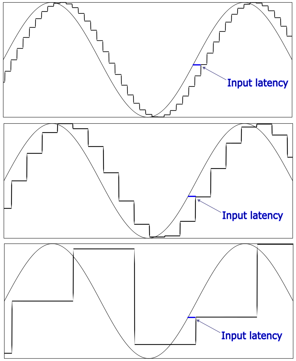
As you can see, when Q gets too low, like in the bottom image, it isn’t a good approximation of the required sine-wave any more.
(if I find time, I’ll try to improve this diagram a bit later on to reflect that the sine wave is output and the the input is just position)
@runger Thanks for this detailed answer and explanation! I am already using it to get some numbers, but something seems missing: I don’t understand how this calculation does not involve the number of stator slots, or indirectly the cogging frequency?
A “good” value of 12 for Q is one way, but it doesn’t feel mathematically complete. If we want the minimum sensor update frequency so that the driver doesn’t lose synchronization, should Q not somehow depend on the number of stator slots? My intuition is, at a minimum we only need to know whether a single magnet’s center is to the left of the slot center, or to the right?
For example, keeping the number of magnets constant at 14, you could have a motor with either 12 or 18 stator slots.
At the same RPM for both motors, a single magnet will have less time to cross the face of a single stator slot in the 18s motor, So should it not require a higher sensor update frequency than 12s?
It’s good observations, and I must admit I don’t know enough about it to give you a really accurate answer - I’m from the software side and don’t really know much about motor construction…
But from my primitive point of view, the stator slots don’t matter - because the motor only has 3 windings in the end, you can only control three phases, and while there are different types of modulation, sine waves are a representative and simple way to think about it.
So while it is absolutely true that the stator slots will affect the cogging, and therefore contribute to the error, which I loosely described as decreasing “smoothness” and efficiency, I wasn’t taking that into account in the above.
If you try to take it into account, without introducing additional new algorithms to compensate for it, then you’d essentially need to increase your control bandwidth (and sensing frequency) to compensate for it just using the FOC loop. This is difficult, normally anti-cogging is done with additional code.
If you wanted to take it into account it doesn’t change the basic approach from above, except this time the frequency you’re targeting isn’t the commutation frequency but rather the cogging frequency.
And here things get a little more complicated, because the cogging frequency depends heavily on the motor construction (nr of poles vs slots). Some infos can be found, for example, here:
https://mqitechnology.com/understanding-and-manipulating-cogging-torque-in-permanent-magnet-brushless-dc-motors-with-isotropic-bonded-magnets/
Taking a common 12N14P configuration, for example, you’d get a cogging frequency f_{t}:
f_{t} = LCM(12, 14) = 84
And
f_s = \frac{f_t R Q}{60}
So for the 12N14P motor, f_s for just the commutation and to reach 1000RPM and a quality of 30 would work out to
f_s = \frac{ 14 \cdot 1000 \cdot 30 }{ 2 \cdot 60 } = 3.5 \text{kHz}
compared to if you want to compensate the cogging:
f_s = \frac{ 84 \cdot 1000 \cdot 30 }{ 60 } = 42 \text{kHz}
Note that going this fast comes with additional complications, because it brings us into a domain where we would also have to run the PWM frequency of the driver (which is producing these waveforms via pulse width modulation) much faster in order to be able to control a waveform at 42kHz output frequency.
This is great, thank you. I guess my question boils down to what happens when Q is 1 ( lets use RPM 1200 for rounded numbers).
Using commutation frequency as input, sensor frequency for 1200rpm is 140Hz.
Using cogging frequency as input, sensor frequency for 1200rpm is 1680Hz.
So, in your opinion: If we have a sensor reliably reporting changes somewhat faster than 140Hz, can we “certify” that this setup will successfully commutate a 14P motor up to 1200RPM (ignoring non-smoothness)?
If not, what method must one use to calculate the minimum value of Q?
hey,
no, Q=1 is definitely too low, you can’t represent a sine-wave with only one sample point…
good question. I would have said a minimum is about 12, and one way (simplistically) to look at it would be to say that the minimum number of distinct output steps to do BLDC commutation is 6 - that’s block commutation, driving the motor with square waves. And therefore, in an indirect and loose application of nyqist theorem we should sample 12 points.
More scientifically you could compute the error by finding the area difference between the ideal sine wave and the approximated sine wave as in the pictures above, and decide on a value of Q where you’re happy with the error metric produced.
Or, you could approach it from a different viewpoint: the sine wave is ideal and has no harmonics - the reproduced sine wave is composed of little square waves, approximating the smooth curve. The lower the value of Q, the longer the time between samples, and the “taller” the steps taken will be. This will lead to stronger harmonics and more noise in the frequency spectrum.
So this suggests another approach where you choose Q based on the level of frequency noise you’re comfortable with.
I’m not strong enough on the maths to write formulas without researching that first… perhaps there are other readers who work with such concepts on a day to day basis and could provide better insight.
And another way to look at it would certainly be from the control theory point of view in terms of the control bandwidth. If you’re trying to make the motor follow a set of velocity (or position) commands, in effect getting it to follow a (one-dimensional) path over time, then how closely you can follow such a path, and how quickly you can change velocity in response to what you measure from the motor will depend on your control bandwidth.
And the control bandwidth of your SimpleFOC system will be strongly correlated to the sensor sample frequency. So another way to choose Q is based on the control bandwidth the use case requires.
Again, I will defer to someone more knowledgable to provide a mathematical foundation for that. ![]()
I think this hits the nail on the head:
My question was always about a mathematically/geometrically rigorous means of knowing this minimum number. When brushless motors came into being, the hall sensor scheme was devised/refined. And we know that for a simplistic single-magnet (across diameter, ie 2 pole), 3 phase motor, we need three hall sensors to commutate the motor reliably across 6 steps.
The meaning of commutating over a full cycle implies getting the north pole of this single magnet back to exactly the same position as it was after rotating around 360 mechanical degrees.
For analysis’ sake, the combination of the 3 halls can be loosely thought of as a single sensor giving a 3-bit output.
So if we actually had a 3s2p motor, and such a composite sensor, this sensor technically only needs to be fast enough to report 6 positions reliably over a single revolution, at the given rpm.
But when you have multiple magnets/pole pairs, the full cycle is not 360 around mechanically, but from the center of one magnet, until the center of the next magnet with the same polarity (hence num pole pairs, not num magnets, because poles alternate).
So your first attempt seems perfectly correct, with the absolute geometrically minimum value of Q being 6 in that formulation. But even the teeniest bit of deviation from perfection will cause loss of synchronization. So a Q of 10 should work for less demanding cases. I also like applying Nyquist theorem to this as a mathematically rigorous way of guaranteeing reliability. In that case Q becomes 12.
To sum up, I will reformulate to simplify so it can help others down the line:
To run a 3 phase motor with N poles at R rpm, the minimum commutation frequency is:
f_c = \frac{NR}{2\cdot 60} \cdot 6 = \frac{NR}{20}
Leading to a minimum sensor frequency in Hz of:
f_s = f_c Q = \frac{NR}{20} \cdot Q
Where Q must be > 1, or ideally more than 2 to ensure reliable commutation.