Hello!
I am having problems with EMI affecting my encoder. BLDCMotor.loopFOC() seems to lock up and not return if the I2C bus has an error. I am able to reproduce this by pulling SDA low with a button. The symptom: motor begins “cogging”, holding in one position. Does anyone know if there is a software way to detect and recover from I2C errors?
I am using the B-G431B-ESC1 with the AS5048B I2C magnetic encoder. I’ve successfully been using this setup for over a year, but due to the inconsistent EMI in my new configuration I have begun to notice this problem.
Things I have tried:
As a workaround, using the watchdog (IWatchdog.h) to force reset the controller fixes the I2C bus, and everything works properly
updating the Wire library so that I can use the function setWireTimeout(). But it seems that the framework ststm32 only has V1.0 of the Wire library, which doesn’t have this functionality.
I am also trying to reduce the EMI, don’t worry . But I’d like to be able to detect this problem so I don’t burn out my motor without having to rely on the watchdog.
Simplified code example, very similar to what I am using:
(except that my full code has the motor moving back and forth)
#include <SimpleFOC.h>
// Hardware params
const int num_Pole_Pairs = 11; // Property of BLDC motor
float electric_Angle = 2.50; //rad
//global Variables
unsigned long last_loop_time = millis();
//BLDC Motor Setup
BLDCMotor motor = BLDCMotor(num_Pole_Pairs);
BLDCDriver6PWM driver = BLDCDriver6PWM(A_PHASE_UH, A_PHASE_UL, A_PHASE_VH, A_PHASE_VL, A_PHASE_WH, A_PHASE_WL);
//Encoder Setup
// MagneticSensorI2C(uint8_t _chip_address, float _cpr, uint8_t _angle_register_msb)
MagneticSensorI2C sensor = MagneticSensorI2C(0x40, 14, 0xFE, 8);
//Current Sensing Setup
LowsideCurrentSense current_sense = LowsideCurrentSense (0.003, -64.0 / 7.0, A_OP1_OUT, A_OP2_OUT, A_OP3_OUT);
//**********************************************************************************************************
void init_PID_values(){
//Set Limits
motor.velocity_limit = 40; // rad/s
motor.voltage_sensor_align = 4; // limits motor voltage during calibration of motor
motor.voltage_limit = 12; // [V]
motor.current_limit = 5;
//Set Motion Control Type
motor.torque_controller = TorqueControlType::voltage;
motor.controller = MotionControlType::velocity;
motor.target = 0;
//PID SETTINGS
//VELOCITY PID SETTINGS - for current foc mode
motor.PID_velocity.P = 0.3;
motor.PID_velocity.I = 5;
motor.PID_velocity.D = 0;
motor.PID_velocity.output_ramp = 1000;
motor.LPF_velocity.Tf = 0.01; //makes job of pid easier
//POSITION PID SETTINGS
motor.P_angle.P = 5;
motor.P_angle.I = 0;
motor.P_angle.D = 0.2;
motor.P_angle.output_ramp = 1000;
motor.LPF_angle.Tf = 0.01;
//CURRENT PID SETTINGS
// Q axis
motor.PID_current_q.P = 1;
motor.PID_current_q.I = 100;
motor.PID_current_q.D = 0;
motor.LPF_current_q.Tf = 0.01;
// D axis
motor.PID_current_d.P = 1;
motor.PID_current_d.I = 100;
motor.PID_current_d.D = 0;
motor.LPF_current_d.Tf = 0.01;
}
//Main Setup Function
void setup() {
Serial.begin(115200);
Serial.setTimeout(20); // ms timeout
sensor.init();
Wire.setClock(400000); //set i2c clock speed to 400khz
motor.linkSensor(&sensor);
//Driver Initialization
driver.voltage_power_supply = 25.2;
driver.init();
motor.linkDriver(&driver);
// link current sense and the driver
current_sense.linkDriver(&driver);
// Select drive modulation
motor.foc_modulation = FOCModulationType::SinePWM; // default
//Current Sensing Initialization
current_sense.init();
current_sense.skip_align = true; // skip current alignment
motor.linkCurrentSense(¤t_sense);
init_PID_values();
//Initialize Motor
motor.init();
// align sensor and start FOC
motor.zero_electric_angle = electric_Angle ;// rad
motor.sensor_direction = Direction::CCW; // CW or CCW
motor.initFOC();
//Reset this variable - otherwise voltage limit gets somehow reset
motor.PID_velocity.limit = motor.voltage_limit; //this is a bug https://community.simplefoc.com/t/pid-velocity-limit-is-always-0-2-at-init-time/1221/2
}
//####################################################################################################################
void loop() {
motor.move(0);
motor.loopFOC();
if ((millis() - last_loop_time) > 500 ) {
last_loop_time = millis();
Serial.println("loop");
}
}
What value are you using for pullups? Instead of trying to fix this in software, I would try to address the hw problem first. This might very likely be caused by the wrong pullup values for the voltages used
Do you have an oscilloscope? If not, have your routed all I2C wires away from the magnets/coils? Ensure that the I2C wires are as short as possible, and with a GND in between SDL and SDA (if using a ribbon)
I’m also addressing the electrical issue, but I’m mostly looking to see if we can recover in the software from a lock-up condition. I don’t want to fry motors because I introduce EMI in a new design, ideally I can enter an error condition and turn off the mosfets gracefully.
But while we’re here:
The I2C wires are probably too long for ideal conditions in this new configuration (90cm). It’s obviously much less than ideal, but I was trying to keep the ESC inside a waterproof enclosure. I may look at moving it as a future design revision
I tried putting 4.7k pullups on SCL/SDA, to little improvement. This is in parallel with the board’s 10k pullups. I went to put even smaller (1k) but I then realized that the board has inline 1.8k resistors from SCL/SDA to the MCU, so that didn’t work. I may pull off the inline resistors and explore this further.
I’m currently at 400kHz I2C bus speed. At that speed, I’m barely getting over the acceptable threshold of 2.1V for HIGH. I bumped it down to 100kHz and the peaks grew to ~3.3V.
The shielded cable I’m using for the motor wires is routed 30cm away from the I2C shielded cable. Both cables have their shields grounded on the ESC side (telescoped). They are each using 28AWG stranded wire. The encoder is powered off of the 5V rail.
The wires do run near some small DC fans, but even when they are unplugged it does not resolve it.
400kHz, 90cm and inline resistors are the perfect recipe for problems
Definitely remove the inline resistors, those are the most likely culprit. Then ensure you have the right pullups for the I2C wire you use (capacitance is an issue, that’s where an oscilloscope helps) https://www.ti.com/lit/an/slva689/slva689.pdf?ts=1688973589547
Lastly, the STM32 family doesn’t have I2C bus recovery, and sometimes the hang is on the peripheral side, so not even a sw recovery is guaranteed to work if you have bus issues.
Definitely remove the inline resistors, those are the most likely culprit.
Do you have any recommendations for alternative values for the inline resistors? I read that they are used to protect from voltages spikes on the I2C bus.
Lastly, the STM32 family doesn’t have I2C bus recovery, and sometimes the hang is on the peripheral side, so not even a sw recovery is guaranteed to work if you have bus issues.
That’s a bummer. I can try the bit-bang method to knock the device off the bus, but only if I can figure out how to add a timeout into the Wire.cpp file. Otherwise, any additional logic I write will never get run. Do you know how to edit the libraries that platformio uses without having your changes get overwritten on compile time?
There is a nearly identical sensor that runs on SPI. I have heard SPI is more resistant to noise, although the stuff I could find on the web did indicate that I2C was actually good for significantly longer runs than that.
You may also be able to get it to give a pwm output. I also had some problems with noise over I2C using this same board, mostly when the motor wires ran near the i2C line. PWM has many downsides as well but it did work ok for me using 1 khz update rate and I think the smoothingsensor thing would help a lot. I used pwm input on this board successfully with an as5600 magnetic sensor. There are posts of mine to be found on the forum.
I wonder if it is possible to put the wires together as pairs like they do with ethernet cables to reduce inductance and if that might help.
Are you sure it’s just one error? One error every once in a while should be easy to ignore, and this is probably already done in software, the smoothingsensor would probably help as it would dampen the impact of erroneous values, however in my experience if the I2C communication is broken the system nearly hangs, as described. It doesn’t actually hang, the I2C communication does eventually time out but it takes a long time and because it has to be called very frequently the system practically stopps.
This is not cogging, that is a different phenomena.
I have heard that if you run I2C extremely slowly that it will get better noise performance than SPI- I haven’t verified this but I heard it from someone who produces their own boards for a living, so might be worth a check. However that does have direct ramifications for motor performance.
If you go in the .pio folder, you can edit the libraries in there and they will not get overwritten at compile time, but if there is any update or you clean the project it will get lost. What I’d recommend is to copy the libs out of there and move them into the libs folder of your project and then remove the library dependency from your platformio.ini.
Like @robca mentions you may have an issue with pullups - you can move to a smaller value for a faster bus pull, this might help you with keeping better voltage levels at higher speeds.
Git-Clone the library to the lib folder of your project. Remove it from the platformio.ini file lib_deps section. Make any changes you like to the lib folder version of the library, it won’t be overwritten unless you use git to do so. Conversely, you can use git to version your changes, submit them back as a pull-request, or overwrite them with the original version if you choose so.
I2C is not a good protocol to use in conjunction with motor control. Even at 400kHz it is much too slow. So the primary recommendation would be to change the sensor (use SPI or ABZ type interfaces).
But the 90cm is itself a problem, and will require special attention to interface type and cable used. If you can shorten your cables, this will help a lot.
If you want to continue with I2C, you might find the following commit useful:
Its on the dev branch of the SimpleFOC library, and would allow you to check in software for failed I2C transactions, and try to software-reset the bus (and stop the motor).
It’s the first time ever that I see inline resistors in the I2C bus. There’s no reason to have inline resistors unless you plan to have a cheap (and poorly working ) voltage divider to adapt 3.3V signals to 5V
There are no voltage spikes on a 3.3V I2C bus. Just short the inline resistors and you will improve your I2C errors
Thanks for the tips, I was able to test out different code ideas as well as some electrical fixes.
Update on progress:
For code:
I tried detecting I2C errors with padok’s PR for exposing errors returned by wire.endTransmission(). I trigged the I2C lockup manually with a button pulling SDA low. This worked, and in combination with motor.disable() I was able to turn off the motor (it may have been lightly powered on still a bit? not sure, it seemed a bit “coggy” when I turned it manually).
I tried exposing Wire.h’s recoverBus() function, and calling that when I2C errors detected.
After running that code, the sensor didn’t come back. Through some testing I tried running sensor.init() and motor.initFOC(), I was able to get my system operating again after an error. The one catch: there was a whining sound while the motor was turning now. I decided to abandon this route.
Instead, my 100ms watchdog is able to reset the controller when we have this I2C bus lock, which on reboot properly unpowers the motor, saving it from burning up.
Edit: For anyone wanting to implement a watchdog using framework-arduinoststm32 with platformio:
#include <IWatchdog.h> // Located at C:\Users\YOUR_USERNAME\.platformio\packages\framework-arduinoststm32\libraries\IWatchdog

void slowFunctionThatWillTriggerWatchdogReset(){
    delay(1000); // Wait 1 second
}

void setup(){
    IWatchdog.begin(100000); // Set a 100ms watchdog that will reset the MCU if
    if (IWatchdog.isReset(true)){
        // Do something. This detects if the watchdog reset the controller
    }
}
void loop(){
    IWatchdog.reload(); // Do not let watchdog expire
    slowFunctionThatWillTriggerWatchdogReset(); // This function takes too long and will cause the watchdog to trigger
}
For electrical:
We added external 1k pullups to 3.3V on SDA and SCL.
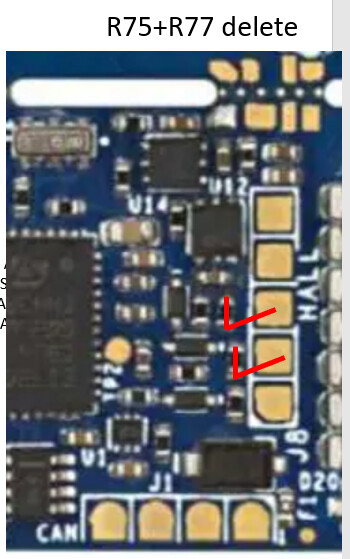
We removed R75 and R77 (inline 1.8k resistors on SDA and SCL) and solder bridged their connections.
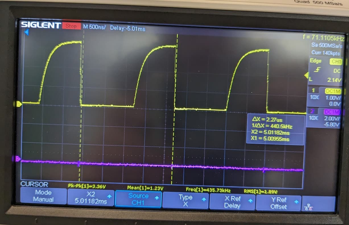
After doing this, we got better performance on the I2C bus (we get all the way to ~3.3V on highs, and to ~0V on lows). Except, there was now ringing introduced.
We then added in 470R series resistors between the I2C bus wires and the B-G431-ESC1’s pins, which took away the ringing. Interesting note for anyone else - we measured 440kHz in this picture, but had set 400kHz bus speed. Seems like a pretty large discrepancy!
I’ll keep monitoring the system to see how often there are get EMI problems now. So far, so good, I have not reproduced the initial problem since these changes!
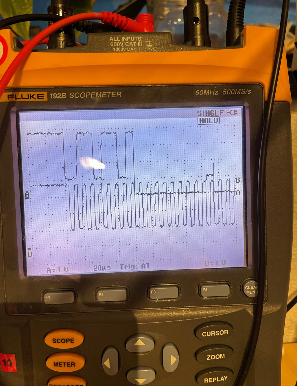
I run the same board with an AS5600. Short cable run (15cm). It mostly works out, but I also have dropouts now and then. I have it running at 1MHz, however from the scope it looks like 100kHz at startup. I thought I had confirmed this to work in the past. Maybe it switches gear later.
I just had a scope on, and realize I need to delete (or change) R75 and R77 as well.
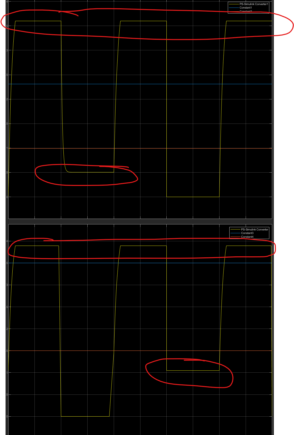
Top plot is voltage at the ESC1 ECU pins (yellow). 1st no pulling on the line, 2nd sensor pulling on the line, 3rd no pulling, 4th ESC1 pulling. Also shown logic high/low for 3v3 device.
Bottom plot is the same, but observed from the sensor (5v0).
The weakest signals look to be from ESC1 to sensor (separation from logic levels).
Ideally the AS5600 should be moved to 3v3. Datasheet says it must be driven different from 5/3,3V operation. Turns out the boards I have are in 3v3 mode. Lucky they did not fry…
Are there any pads where 3v3 can be found? Alternatively A+/H1 could maybe supply the sensor, but will need R74 and R71 bypassed.
That trace doesn’t look so bad. Are you sure the AS5600 is wired correctly etc? You have to change things if you run it on 5 volts vs. 3.3 volts. Also the direction pin and other stuff may need to be grounded.
I would just try printing out the sensor readings while running the motor in open loop and see when it flakes out. You might have to read it with a separate microcontroller, I like the raspberry pi picos.
 . But I’d like to be able to detect this problem so I don’t burn out my motor without having to rely on the watchdog.