Hi, all.
I’m messing around with the BLDC-SHIELD_IFX007T shield, which I am happy to see is a SimpleFOC-supported driver. Really wanted to get my hands on something with better heat dissipation than the B-G431B-ESC1, and ordering a SimpleFOCPowerShield from China would take a while. I’ve already soldered all the necessary connections and resistors and done my due diligence.
Or so I thought. I looked at the SimpleFOCPowerShield’s schematic and example sketch to help me figure stuff out, because the driver stage for the two boards is very similar, and I ran into two problems:
1.) According to the SimpleFOCDocs, the Arduino Uno only supports in-line current sensing, as does the SimpleFOCPowerShield, and the BLDC-SHIELD_IFX007T shield supports (only?) low-side current sensing?? Am I already doomed here? If not, what’s the correct initializer/definition for current sensing using an Uno and this shield? I’ve got the rest of my main.cpp written, just don’t know that bit.Edit: That’s correct. No current sensing, but board should still work.
2.) According to the SimpleFOCDocs, the Arduino Uno has a fixed PWM frequency of 32kHz, but the IFX007/BTN8982 half-bridge MOSFETs only do 15kHz? If it’s not perfect, too bad. As long as it works.
Following this thread regarding the PowerShield, I read that it’s “completely inspired by the Infineon board”, so I’m really hoping someone has got it working and has a working sketch somewhere.
Edit: Found my answer in this thread: there’s no current sensing support for this board because it uses the high-side current sensing topology, but it should still work. I fail to see how when current is never sensed and there are no hall sensors, but I’ll read more and try with hall sensors and find out. Fingers crossed.
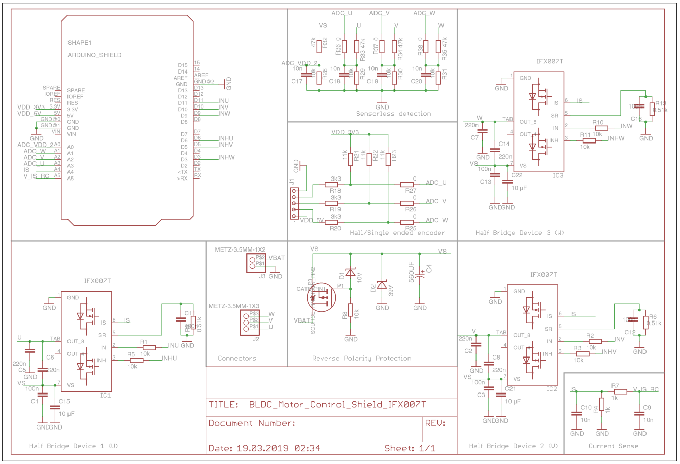
Oh, also, why is the sense resistor R4 on the Infineon board 1kΩ?? It definitely looks different to the shunt resistors I’ve seen on other boards, too, which are in the mΩ range.
Edit: High-side current sensing topology. SimpleFOC doesn’t support yet. May never. Very inflexible design because it requires great synchronicity between PWM triggering and ADC triggering. Super hardware-specific. Read here if curious.
Also, how do I figure out what value to put for “current-sense op-amp gain”? I’m wondering if in my case this will be a really small number if the current-sense resistor is really large?
Edit: It doesn’t apply to the Infineon board, but I’m very curious to know for the future. Is this a number typically given in a board’s technical documentation/user manual?
A big thank you in advance to any helpful responses!
Schematics for comparison (top, Infineon; bottom, SimpleFOC):