Hi guys, Sorry for going off-topic. i have a question about BLDC Phase Signal.
What happens to the phase waveform when the speed of a BLDC motor increases? Does the signal in the BLDC phase have a direct relationship with the duty cycle applied? Is it directly proportional, inversely proportional, or not related at all?
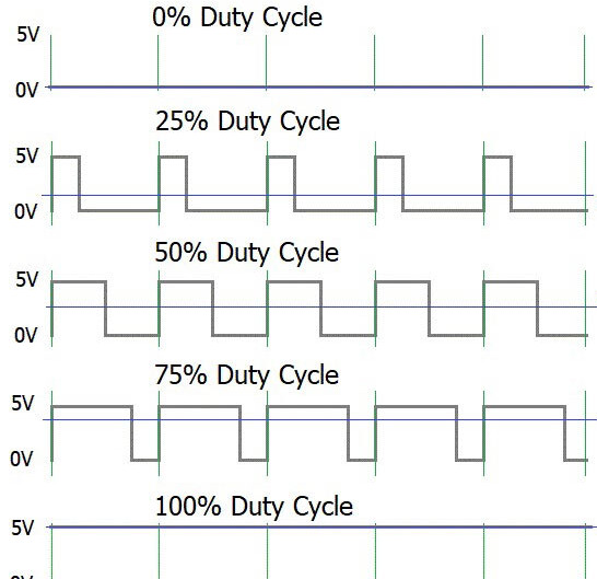
here i give an example of duty cycle
should be the trapezoidal BLDC phase signal directly proportional with the duty cycle given in each MOSFET? or should it inversely proportional, or maybe not related at all?
Good day sir @Candas1 ! thanks for answering my question but i still not sure yet about the switching of the MOSFET effect to the phase voltage, i have open and try the simulation but i’m not sure yet. could you please, conclude it for me sir?
i know that the wider (bigger) duty cycle given to the mosfet it makes the switching faster (that means the faster the speed of bldc rotation) did it also make the width of the phase voltage wider? or it should be narrower?
Sorry i’m still hard to understand the simulation, that would be good if you could answer my question above.
Thank you sir
I think I answered your question in the other thread.
I think you’re confusing the PWM waveform, which is a way to output an analog voltage from a digital system, and the commutation waveform, which is the pattern applied to the phases using these analog voltage, and is used to drive the motor.
Here in green the commutation waveform (sine) and in blue the PWM that generates it:
The speed of the motor is determined by the frequency of the commutation waveform, e.g. the green waveform. The frequency of the PWM does not normally change.
The duty cycle of the PWM will determine not the speed, but the level of the analog voltage seen by the motor (the y-coordinate of the green waveform).
In terms of the commutation it is only the frequency of the green waveform that matters for the motor speed.
This is bound to be confusing for a lot of people as the voltages for six step commutation can be square wave, and many people think of controlling motor speed in terms of pwm. I think we need a small, well written book, which I would entitle “making the turny thing turn”. To be fair it’s not as simple as people want, but Arduino was made in part for artists and stuff, and we have to respect that none of us know much outside of our areas of expertise. Enabling people to rapidly get stuff done is good… Another project for another day.
That’s why I shared the Space vector PWM Intro, I think it’s quite good.
It took me a lot of reading and rereading of the same documents over and over again over the last few months to understand some of those concepts.
I am not sure there is a shortcut.
There is a lot of content out there for those that are searching.
The EBICS firmware has a list of useful links, such list could already help people maybe.
There are a lot of videos also, like this playlist, this and the following parts, this playlist, this playlist