BLDC Omicron 24V 20A New Board

We are in a new lockdown. In honor of this, having some spare time, I created a new board.

I called it Omicron. Haha.

This is a proof of concept / educational board, chances to work are about 1 out of 4. The challenge was to squeeze it as small as possible. This is a 27mm X 40mm board. All I/Os are present, 2 SPI ports, SWD for programing, and a UART. Also, I used the smallest STM32 chip as well as the somewhat questionable UP9636PQMY mosfets. I calculated, for a 2 layer PCB you could possibly draw 20amps before it literally melts. There’s current sensing, too, using INA199 with rc filters.

If I get the time I will fab it and test it.

3 Likes

Nice, this looks like a contender for my M5Mouse project. Could probably squeeze it into the M5Stack footprint

Are there I2C pins for working with I2C Commander?

Nice. I didn’t even know micromice are still a thing today, I thought they peaked way back in the 90s/early 2000s when the MIT team found out they could cut corners to optimize the trajectories. Are the rules still the same?

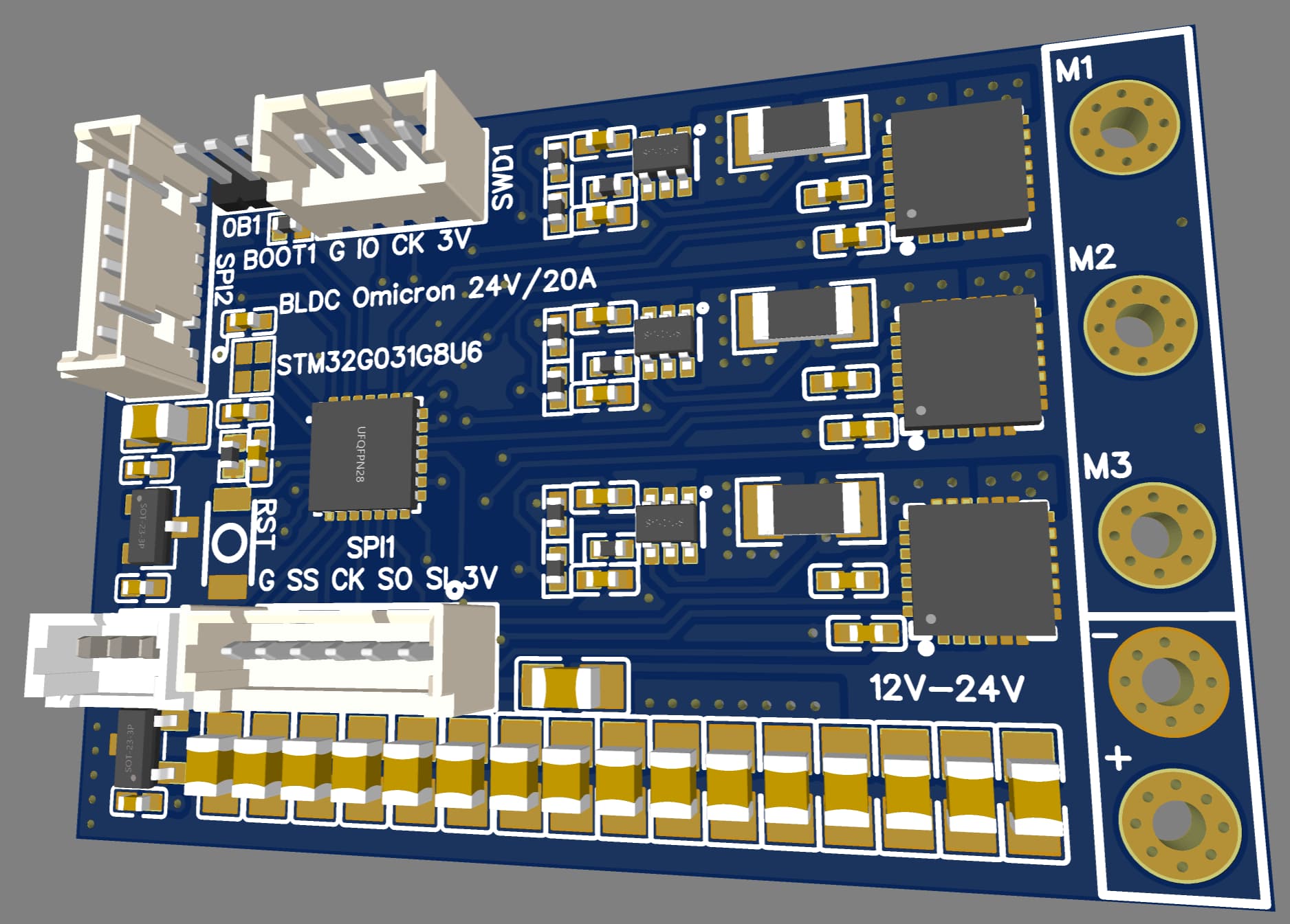
Let me check. I didn’t really go all out, since I tried to keep it two layers. For a micromouse, which requires such low current, you may be better off with pairing the MCU with a fully integrated driver such as one of TI’s DRV83xx, the DRV8316 comes to mind, you can create a really tiny soup-to-nuts board. Problem is, they are all out of stock everywhere, who knows when they come back.

Another solution is to stack them on top of each other with castellated holes, effectively creating a dual layer board.

No I2C pins, since I prefer SPI to I2C. This MCU has only 28 pins and the I2C pins are already taken by other I/Os. Let me check if I could expose I2C pins however, I have doubts due to the low pin count on particular package. Give me an hour.

Edit: OK, I am a bit confused, which one is the target size, the 50x50mm or the smaller Olimexino footprint inside? Also, what is the Olimex connection there?

Edit2: I can expose the I2C but that will remove the SPI2 which I want to use for CANBUS interface.
It is conceivable to dual-use SPI or I2C on two connectors, one at a time, but it will take more space.

Edit3: You know what, since SPI2 shares pins with I2C, one could just use the 5-pin SPI2 connector but draw signal from only two of the pins for I2C connection. I could add the pin assignments to the silk screen so people know which pins to use for I2C. It’s a have the cake and eat it too situation.

Edit4: One very important thing to remember, this package for G031 shares the boot pin with the SWD/IO pin so you must use the so-called connect-under-reset programming, that’s why I added the RST switch. Normally SWD programmers won’t access the chip directly using the soft reset due to pin sharing.

1 Like

I wonder if its suitable. The bandwidge and SR is low so it might not sultable for handling large common mode transients. Theres around 20us overshoot for ina199 while ina240 only got 0.1us.The output voltage may never have the time to get stable
Please oscilloscope it when testing.

1 Like

No it is not, I am aware of this. But everything else is out of stock. I’m using it only as a proof of concept. I have INA254 with integrated resistor however I’m saving those for when the board is finalized.

INA225 however is in stock, I have another board with it to check suitability. Need to find the time to complete testing.

Can i produce it ?
Is it open-sourse?

Public domain. You can sell it if you want. I don’t care.

I could share the schematics and you could order it. Caveati emptor:

  1. It’s not going to be very cheap. I did not select the components based on cost but size and availability.
  2. The G031 chip is difficult to program by amateurs / hobbyists due to pin assignment and connect-under-reset flashing. The challenge is to run both SPI simultaneously.
  3. I believe I was very careful selecting the PWM pins on the correct timers, however it’s not guaranteed it will work as it’s not tested at all.
  4. The INA199 current sensor may not be the best choice.
  5. The LDOs may not be the best choices.
  6. I have no clue about the MOS heat dissipation, or even BLDC suitability.

Let me know, if you are still interested I could post the public link, you could clone it and direct order on JLC, they’ll solder everything for you. All components are in stock, at least until three days ago, hahaha. These days who knows.

Please let me know.

Cheers,
Valentine

I see a problem that would stop me from buying it :
These tiny connectors need cables that you can’t make or buy, unless you have very deep pockets.
Another reason to design my own boards.

@Jan_Donker

These are very widely available PicoBlade Molex 1.25mm pitch connectors, you can get them for like a few pennies, all pin count sizes:

https://www.amazon.com/Connectors-Pre-Crimped-Compatible-PicoBlade-Silicone/dp/B08RMQP6YP

Edit: Few pennies per crimped cable, obviously.

I think I want one of these for Christmas :slight_smile:

Is there a reason that robotics-oriented drivers always have such a small percentage of the board devoted to the MOSFETs? Most drone ESCs devote an entire side of the board to them, giving much higher current capacity for the size. I have some old DYS SN40A ESCs that are particularly beautiful. Rated for 25V 40A, and only 17x46mm board dimensions (plus a 10x18mm electrolytic capacitor soldered on the end, making the total length 60mm). It doesn’t even use the smallest components on the top side, so it would likely be possible to rework it to make room for SMD capacitors, or more connectors. It does have solder pads for firmware flashing, which can be used to read hall sensors for closed-loop control… if I can ever get my firmware to work well. Maybe I’ll see if I can get SimpleFOC running on it next time I have a go at it :slight_smile:

Not really. Robotics (with a very few exceptions) have no size or weight restrictions. The use case is different. Drone boards do. Designing a small board requires very many sacrifices to be made. Small footprint is also expensive to design and hard to SMD. In addition, I guarantee you those boards are not 40A. If you pull 40A/25V (1000W) from a board like that for more than a few seconds it will smoke. These boards you show are at most 10A for robotics, and 40A pulsed for a few milliseconds. Basic math: The board you show is 17mm/1oz, and the copper can carry 25A continuous before it literally melts. Realistically, I’d divide that by 2 unless you have awesome cooling. So they are already lying to you. One more thing. Drones PCB are not like robotic motors where you need to hold angle and torque, they turn and re-duty all the times. Robots need to hold angle, so one or two of the phases are always at nearly 100% duty. Take the 17mm and divide by 3, you end up with what, 8A before it melts the copper? The drone board you show, if you pull 10A holding angle/torque with FOC, will smoke in a few seconds. MOSFETs will be fine, but the solder will melt.

Yes, you could use a drone board for robot FOC but you probably need to re-rate the board may be 5, may be up to 10 times lower.

Thanks for the response.
Certainly 40A is more of a peak current rating than continuous, but nonetheless that board manages to squeeze twice the MOSFETs into a similar size as yours, so I thought it might be of interest. Or do you mean to say that the current capacity of the MOSFETs is wasted because the resistance of the PCB traces becomes the limiting factor?

That board comes with a hunk of aluminum stuck to the MOSFETs, so that should help spread out the heat when a single phase is running. Although I was planning to use the aluminum structure of my robot as a large heatsink for it, hence why I took it off.

I disagree on that point. Sure something like a stationary robot arm or CNC machine can have a big box of electronics sitting next to it, but anything that moves around untethered will benefit from smaller controllers. Especially since robots often have larger numbers of them than drones.

I really need to learn how to design these things myself so I can better understand why nobody does it the way I think they should :slight_smile:

You could squeeze the chips without a problem. Question is how do you get the current and heat out? I could design a two sided board as big as 6 mosfets footprint but that woul be impractical.

Exactly. There are ways to do that with thick copper or copper bars but thats not a DIY hobby stuff, it costs a lot. And these boards have no protection.

Can’t spread the heat from copper planes melting inside the pcb plastic. You can drain the mosfet heat but the copper will build up heat a lot faster you could drain out. Hence, large boards are needed.

Agree. Only one way to prove a point: make it.

You should give it a try!

IMHO, designing small boards is really quite hard (and therefore a really nice, interesting kind of problem). It combines the already tricky requirements of component selection and diving into data-sheets with a really hard topological problem of where to put everything.

The problem is a lot harder than it sounds at first glance: it’s not just the components which need to fit, but also all the vias joining them. And unless you want to catapult your board costs into the stratosphere, you will be using only large-ish through-hole vias. So each via removes a bit of space on both sides of the board…
Add to this the fact that just conducting 20A of current will heat a 2Oz (already double the normal) copper track of 1mm width (very wide!) and only 10mm length to more than 400°C - melting all the solder around it etc…
So for the power carrying tracks you need very short, wide tracks, need to run them on the outer layers, and probably shouldn’t use vias on them. As Valentine has noted, many high-powered ESCs contain “bus bars” - copper bars screwed and soldered onto the board to serve as the current carrying tracks.

Also I’d note that most drone ESCs I’ve seen don’t have consider cooling at all. They’re designed to power fast-flying machines, and the forced air from the propellers and flight motion always cools the ESC. This is in contrast to most stationary driver modules, or the ESCs made for RC-Car racing, which at a certain power level always come with fans and heat-sinks.

And finally I would say that about 75% of the Amp-rating of any given drone-ESC is advertising, and only 25% actually usable amps… They do things like adding up the amp ratings of all the FETs, but that’s not a current that can ever actually flow through them.

1 Like

… by putting the MCU and driver on top of the sizzling hot mosfets. Which reduces their lifetime by about a factor of 100.

Crashing kills them much faster than heat. :rofl:

Yeah, I wasn’t about to comment on that :rofl: like broiling burgers on a summer grill.

image