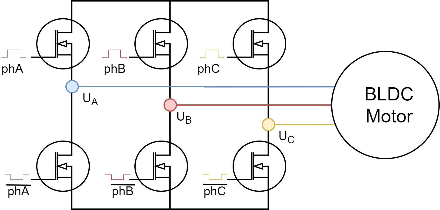
I am familiar with BLDC drivers and know how to drive the motor with 6 MOSFETs (at least I think so).
So to keep it easy lets say we use rectangular signals which can be +Vcc, GND or -Vcc. This would work like shown in the AN5423 from ST:
(1) So first of all do I understand it right that if you don’t have a negative power supply (which is the case most of the time) you reverse the current flow through the individual coils by commutating the direction of the voltage supply?
(2) To drive the motor the way mentioned in (1) you always need to either drive each mosfet individually (like in “6PWM”) or to only drive each H-bridge by having negated low side driver inputs like in the picture of “3PWM”. Is that also correct? That means for the second type you also need enable inputs for the H-bridge to get a tristate output?
(3) So, is it possible to drive the BLDC motor by only using the H-bridges without driving the individual MOSFETs or having an enable input? I think about offsetting the voltage to have the zero crossing at VCC/2 by using 3 sinusoidal signals (e.g. sinus signal with V_max/2 DC offset).
And when using that kind of offseted signal on each phase (by means of PWM) you can keep the neutral point of the coils at zero by superpose.
(4) As mentioned here, the enable input is optional. If not using the technique from (3), how can you drive the BLDC motor with just 1 enable pin or with even no enable pin by just using the H-bridge without HighZ state?
Thanks for any help in advance!
Best regards,
Florian
This is true, the true trapezoidal or 6 step control signals do require the high-z state. However, as we are mostly working with the sinusoidal PWM signals, where the commutation is sinusoidal and there is no 0V state of the phase voltage, the enable pin per phase is not mandatory.
Also bare in mind that the signals that we are sending to the motor are actually the PWM signals, we are not opening and closing switches as in the stm’s diagram from above. The diagram from above is fine if you really wish to set the full voltage of your power supply to your motor, (the PWM duty cycle of 1.0).
So if you think in terms of PWM, the 6 step commutation requires 0 voltage on one phase, which would usually require the high-z state, but you can actually set 0 voltage using PWM.
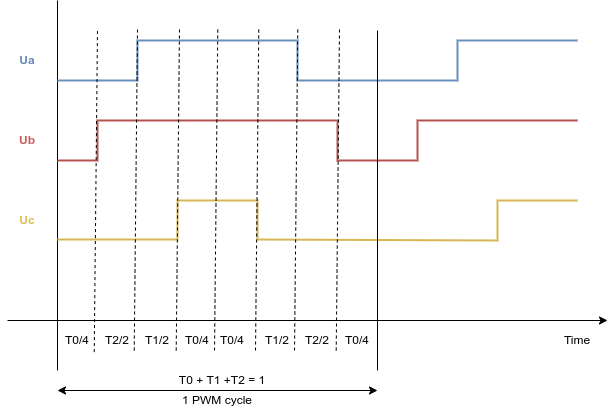
What we do is that instead of using the ground to be 0, we shift the 0 of the PWM to be half of the duty cycle - 0.5 for all the phases. In that way, you can have positive and negative voltage set to your motor phases by setting the duty cycle value in range [-0.5, 0.5].
I have an old image depicting it a bit, maybe it can help. basically by fluctuating the voltage in between the ground and Vdd you can effectively have -0.5Vdd to 0.5Vdd voltages on your phases.
thank you very much for the detailed description! Now I think I understood it way more.
So instead of reversing as with trapezoidal driving, the differences between the PWM values (e.g. phase A has a higher PWM value than phase B the current flows from A to B and the other way round) are used to quide the current flow direction.
That means if I have a 24V motor on a 24V power supply the phases get a maximum voltage difference of 12V which means only about half of the torque/power?
So, I have two more questions concerning your answer:
(1) At the SimpleFOClibrary, do I only need to set FOCModulationType::SinePWM to not have to use enable pins or is there more to do?
So with sinusoidal PWM I only need one driver of that kind, because I don’t need tristate mode and I can set the EN inputs to always high (like OUT1, 2, 3 to the phases)?
Actually you do not need the enable pin at all.
I would suggest their use if using the trapezoidal modualtion strategies, but honestly those modulation strategies are not well tested and I would not suggest their use if you’re a beginner, or if you have other option
SimpleFOC willl not ask you for enable pin and it will use the PWM to modulate the phase voltages, without setting the high-z state.
ok, I understand, so one should always go with sinusoidal PWM? Is 6-stage commutation even used in common applications?
Yes, I know that these drivers are not very good, but the are the only drivers I have laying around.
I have another issue:
the initialization fails. It says “Failed to notice movement”. The motor shaft is moving about a quarter revolution forth and back. On the motor phases I measured a changing PWM signal each and the hall encoders are working perfectly (high or low depending on the rotor position.
I also tried to turn the shaft additionally manually while initializing, which leads to a succesfull initialization (with of course wrong alignments and so on)…
This is my code:
#include <SimpleFOC.h>

#define PIN_PWM1  2
#define PIN_PWM2  3
#define PIN_PWM3  4
#define PIN_HALL1 41
#define PIN_HALL2 42
#define PIN_HALL3 43

#define NUM_POLES 4

// BLDC motor & driver instance
BLDCMotor motor = BLDCMotor(NUM_POLES);
BLDCDriver3PWM driver = BLDCDriver3PWM(PIN_PWM1, PIN_PWM2, PIN_PWM3);

// hall sensor instance
HallSensor sensor = HallSensor(PIN_HALL1, PIN_HALL2, PIN_HALL3, NUM_POLES);

// Interrupt routine intialisation
void doA(){sensor.handleA();}
void doB(){sensor.handleB();}
void doC(){sensor.handleC();}

// velocity set point variable
float target_velocity = 0;
// instantiate the commander
Commander command = Commander(Serial);
void doTarget(char* cmd) { command.scalar(&target_velocity, cmd); }


void setup()
{
  sensor.enableInterrupts(doA, doB, doC);             // initialize sensor sensor hardware
  motor.linkSensor(&sensor);                          // link the motor to the sensor

  driver.voltage_power_supply = 24;                   // power supply voltage [V]
  motor.voltage_sensor_align = 8;                     // motor align procedure voltage [V]

  motor.linkDriver(&driver);                          // link the motor and the driver

  motor.foc_modulation = FOCModulationType::SinePWM;  // use sinusoidal PWM modulation


  motor.controller = MotionControlType::velocity_openloop;  // set motion control loop to be used
  motor.torque_controller = TorqueControlType::voltage;     // set torque control loop to be used
  motor.motion_downsample = 0;

  // velocity PI controller parameters
/*  motor.PID_velocity.P = 0.2f;
  motor.PID_velocity.I = 2;
  motor.PID_velocity.D = 0;*/

  motor.voltage_limit = 20;                           // default voltage_power_supply

  motor.PID_velocity.output_ramp = 300;               // jerk control using voltage voltage ramp (default value is 300 volts per sec  ~ 0.3V per millisecond)


  motor.LPF_velocity.Tf = 0.01f;                      // velocity low pass filtering time constant

  motor.modulation_centered = 1;

  Serial.begin(115200);                               // use monitoring with serial
  motor.useMonitoring(Serial);

  // INITIALIZATIONS
  driver.init();
  sensor.init();
  motor.init();
  motor.initFOC();

  command.add('T', doTarget, "target velocity");      // add target command T

  Serial.println(F("Motor ready."));
  Serial.println(F("Set the target velocity using serial terminal:"));
  _delay(500);
}


void loop()
{
  motor.loopFOC();

  motor.move(target_velocity);

  command.run();
}
Is there something wrong with the code?
Thanks for any help
Best,
Florian
EDIT:
Maybe the interrupt is not working properly…
I added the following code to HallSensor.cpp:
You’re right, that is a great question. I am not sure how kV is calculated. If it is calculated using the voltage vector value or using the peak to peak value.
If it is calculated using the voltage vector, then it’s true that we can only reach the velocity of half of KV * battery voltage. However, we do allow for a bit of saturation of the sine waves so it would be more like 0.7KVbattery voltage.
On a side note, if the kV would be calculated with the voltage vector and not peak to peak, the standard ESCs would have the same issue. They could reach only half of the KV specified spped. Unless I’m mistaking and they have full bridges instead of half bridges.
Well in my recent experiments with a 55 Kv motor I could easily exceed the specified max rpm (with very low load though) with SimpleFOC, so I guess, Kv calculation is based on peak to peak values. Also, if it wasn’t, I am sure, someone would have noticed by now and raised the point.
Thanks! That saves me the trouble of setting up a test. I do have a B-G431B-ESC1, but I’ve been a bit skittish to try it out for fear of burning it (even moreso now after hearing about so many of them dying for no reason at all in the BEMF thread).
Yeah, I was wondering if you knew which way the kv was calculated. But according to Grizzly’s test, it probably is possible to reach 2x battery voltage x kv using 6 step commutation. When I was trying to write custom hall sensor position control firmware for common drone ESCs, my commutation cycle would only apply voltage between two of the motor wires at a time like Figure 1 in the first post of this thread. So for example T1,T4 and T2,T3 can apply full battery voltage in opposite directions. It gave smooth motion with open loop stepping on a fixed time interval, but I never did get it to run reliably with the sensors. Probably some combination of sensor placement accuracy, lack of filtering capacitors on them, my crude current limiting (changing PWM duty based on motor speed), and other software problems.
I’ll probably try again though. Previously my only debug output was jittering the motor to make beep noises, but now I have a little OLED display. And precisely positioned hall sensors with the recommended filter capacitors.
Another thing I always wanted to try is adding intermediate steps to reduce torque ripple and double the resolution for zero-speed position holding. For example inbetween the first two steps, you could do T1,T4,T6, feeding positive voltage in through wire U, and out through both V and W. I think that would result in 3/4 the resistance though, so it may actually cause torque ripple in the other direction unless you reduce PWM duty by 1/4 during the intermediate steps.
And then I had the idea to switch on all 3 transistors at the start of each PWM pulse, but switch one of the two that have the same polarity (T4 and T6 in this case) off sooner so more current flows one way or the other to gradually move between step 1 and step 2.
It’s entirely possible that those ideas are total nonsense though If everyone else has been using 50% PWM as neutral and higher/lower duty as positive and negative voltage, that’s much simpler. I just couldn’t find any specific information on what it was I was trying to do, so I took my best guess given the hardware available.


