BEMF sensored SimpleFOC board (a.k.a. sensorless)

Hi everyone.

It’s been a while, but a lot has happened.

If anyone is interested in dedicating time on BEMF sensored addition to SimpleFOC (I really don’t like the word sensorless) please let me know. I’m investigating the hardware required and have a board in production I will test with one of the existing ESC firmwares floating around to see if the hardware design is feasible.

I will make one (two, three?) and send it to whoever is willing to help with the software dev effort.

@Antun_Skuric , @runger please let me know if you are interested.

Cheers,
Valentine

1 Like

Hi Valentine,

Why BEMF if I may ask ? If I understood well the BEMF can be measured only when one phase is not driven (so with trapezoidal only ?) and the BEMF is high enough.
This could be tested with the b-g431-esc1 also.

I have a “working” Flux Observer sensorless implementation, but I am the only one who tested it :sweat_smile:. It estimates the BEMF based on the applied phase voltage and the measured phase current. So this only works when the BEMF is high enough and the motor is driven. It doesn’t add much computation.

And copper280z has a working implementation of HFI, it works even at 0 speed but it only on motors with Lq - Ld that is high enough. This requires high frequency FOC to be silent.

Flux observer and HFI don’t require BEMF sensing.

Hi Valentine, that looks cool :sunglasses:

I would be up for adding a BEMF based mode to SimpleFOC… I take it the board has voltage sense? Or is it designed with comparators?

@Candas1 i think BEMF is interesting mainly when you want to go very quickly - then the price of a controller capable of FOC at the needed speed can sometimes be prohibitive. BEMF can be implemented fairly cheaply and doesn’t need much MCU power.

1 Like

Hi @Copper280z ,
What is “HFI” and @Candas1 can you tell us more about your “Flux Observer” commutation, do you have SimpleFOC working with it?
Cheers,

awesome to see some fresh Valentine designs again :smiley:

@Valentine Could you share the schematic, I could be interested in a board. I also have some “sensorless” BEMF code for the ESP32 that I could share …

Yes I’m fully aware of the shortcomings. However many people could benefit from cheap copter ESCs. Also true sinusoidal BEMF FOC is quite interesting from control theory point of view.

Last but not the least BEMF FOC can make the motor go really vroom vroom at high RPM! Conventionally sensored FOC has a problem there.

I will post a link to the schematics since I see interest. Also as I said, I will send one or two boards to whoever is willing to work on it. The board will need a little external extra protection and bulk capacitance from the user, I will not include those.

HFI is also very interesting if anyone is keen, I can design a board for it.

Cheers!

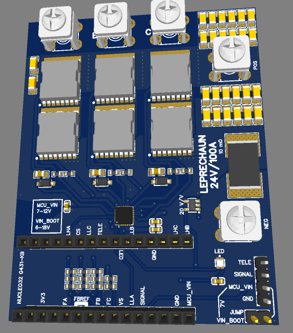
Yes the board has both current (input low side with a 10mO resistor and 20v/v unidirectional amp) as well as voltage sense attached to the high side of the mosfets. The BEMF virtual ground is hooked to two analogs for comparing.

The BEMF and voltage sense is done via 10 to 1 voltage dividers.

I modeled the board and pinouts after a well-known and widely used BLHELI32/AM32 ESC pinout for G431 / Fortior combo.

I will post a link to the schematics since I see interest. Also as I said, I will send one or two boards to whoever is willing to work on it. The board will need a little external extra protection and bulk capacitance from the user, I will not include those.

First I want to make sure the board actually works, before we go a little too wild here. Give me couple weeks, we are here to stay, no rush.

Last but not least the board takes G431 STM32 Nucleo-32 dev board, this is for educational and development purposes. You will need to get one. This also allows people to hook up any other external MCU with Arduino Nano footprint matching the pinouts, or just use jumper wires from another board.

Cheers,
Valentine

High Frequency Injection.

https://trace.tennessee.edu/cgi/viewcontent.cgi?article=7420&context=utk_gradthes

https://www.jstage.jst.go.jp/article/ieejias/126/11/126_11_1572/_pdf

Cheers,
Valentine

Many thanks for that. Look forward to you getting a board running. What voltage/Current will your divers handle?

Also, what will we need to program the board through PlatformIO?
I will definitely be interested in a board to help with the software.

1 Like

My G431 board has arrived … :grin:

1 Like

Hi all I don’t check the forum much so I just saw this! I’m interested in a board design targeted at this use!

HFI doesn’t require anything special, only a really clean/low noise INLINE current measurement with low filter delay and a fast MCU. As everyone else has said, BEMF observer based methods (flux observer style and traditional esc BEMF sensing) are great for going FAST, they’re also more robust than HFI in a couple of ways. It also doesn’t really need anything special other than a good current sense implementation.

Inline current measurement is super important because for the preferred HFI implementation, but low side is supported as well, it just makes an ear splitting my painful noise. With inline sensing I run injection at the PWM frequency, I measure current at v0 and v7 in order to demodulate the high frequency current response. With low side I can only inject at half of the PWM frequency, and due to constraints with the interrupt timing you can’t just double the PWM frequency.

I think to do this really well and somewhat generally, I’d want adjustable current sense gain. Something like the max49925 that @VIPQualityPost used on the LPS with the gain pins connected to the MCU.

My ideal board would also support at least 40V input. Reason being is that high inductance motors have a small current response per injected voltage, so you either need to be able to reliably detect small changes in current, or inject large voltages, or both. The demos I show below are using gimbal motors with ±15V injection, and 33v Vbus.

My HFI port currently supports pretty much every STM32 that sfoc supports, and I’m adding support for more families. I’ve found that time in the ISR scales pretty much exactly with clock frequency, even comparing M4 and M7 CPU cores. Right now I’ve done the most testing with the f446 nucleo at 180MHz, but the G4 at 170MHz also works well. The f746 at 216MHz saves a microsecond or two vs the others but is a much more expensive chip, and if something faster than an F4/G4 is desired we’d be better off using an H5/H7 once @Candas1 or I port current sensing to them.

I’ve also got a variant of the HFI code that supports dual motor HFI, the HFI part hasn’t changed much, but there are some hacks to get the timers and ADCs to init properly. I built a copy of Antun’s balance bot, but with no encoders, to demonstrate how well it works.

Here’s a link to my PIO testing project along with a link to the HFI fork of sfoc.

4 Likes

This is super cool! :rocket:

Is this the first working HFI for simplefoc?

I think this warrants some heavy thinking about how injection/currentsensing should be integrated.

Some thoughts…

  • It would be nice if we didn’t need a new HFIBldcMotor (a lot of the code is duplicated)
  • Perhaps we need a new linkInjector() type pattern?
  • As this is so tied in with current sense, some of the code you written could be moved into current sense classes. Furthermore, perhaps current sense classes can (optionaly) implement Sensor.h

Well done for this, it really looks like a big contribution to SimpleFOC. :heart:

1 Like

There’s been a bunch of discussion on discord about how to integrate it, it’s tricky for a couple of reasons.

First, it’s very performance sensitive. In order for that balancer to work it’s doing the equivalent of calling loopFOC, in foc_current mode, at >80kHz. Any pattern that either involves recalculating things, or significantly more branching should be considered undesirable. Right now it’s only really useful on the fastest STM32’s, the slowest that might have a shot at running it reliably with enough overhead to be useful is probably the f401 at 84MHz. I’d like to find some more time by optimizing the setPwm function, it takes significantly longer than necessary at ~3us last I looked. Beyond that to allow it to run on more chips we’d need to consider fixed point/integer math instead of floats.

The other reason integration into either the sensor or current sense classes is tricky is that to accomplish the injection and demodulation you need access to the electrical angle, unfiltered current sense values, motor parameters, the driver frequency, and setting the driver pwm. You also end up needing to give everything a pointer to everything else and it started to look like a mess. The default filters (velocity and angle) in the motor/sensor class would also break HFI tracking if you relied on the motor class and put HFI in a sensor class, the solution there is for HFI to track angle, but then you have the same value duplicated in multiple objects, but with different filters, so they’re not actually the same. Putting it in its own motor class made it a lot easier to manage. Also, conceptually I like to organize classes that emulate hardware so that the hardware boundaries and class boundaries vaguely line up, and the physics that make HFI work actually happen in the motor.

All that said, I’m really pretty new to writing c++ and would be more than happy to see how someone else would manage integrating this how you describe.

On code duplication, there’s a lot of stuff I left in the HFIBLDCMotor class for compatibility, but it never actually gets called. For example loopFOC just takes a fast path return if HFI is on. I think a good way to reduce that is to refactor things like the sensor alignment, open loop, etc to be compatible with both BLDC and stepper motors and move those into FOCMotor, possibly with a weak ref.

If we accept a motor class for it (I proposed putting it in the drivers repo) then the rest of the changes to the library are near zero. The driver class needs a getPwmState function, and the current sense class needs to provide a user call back function that’s executed in the ADC ISR. Additionally we’d need to change the implementation of inlinecurrentsense to synchronize with the driver, unless we’re ok with my compiler define hack in the low side current sense. Otherwise that’s pretty much it.
2 Likes

Hi Guys,

FYI, I have been working on a cheap sensorless design which I currently am testing, initially just doing 6-step, with the idea of porting to SimpleFOC.

So far I have achieved reliable commutation down to 30 RPM, complete with phase correction (i.e 30deg after zero cross). On startup,this means about 1/2 turn of the rotor in open-loop, before closed-loop kicks in. Tested between 30rpm and 4000rpm.

The commutation is stable from Vmotor of 12…48v in testing. So it’s looking promising. My driver board won’t go higher in voltage, so can’t test further.

I also only tested on 4-pole motor, I need to get hold of some higher pole motors to test further. It’s a work in progress. :slight_smile:

1 Like

@bmentink

Im pretty close to completing my board, will post video later. I can test your code or send you a board to test.

Cheers,
Valentine

Hi @Valentine,

Not sure feeding the code would be useful, as the hardware is quite different, I feed directly to 3xADC with some custom circuitry that does not have any analog filtering. All filtering and other processing is done on the micro (majority filter … no delay).

Also I have tested on a RP2040. So I will need to do some porting to ST…

What would be useful would be the schematic, so I can see how to interface, a board would be great, if you can spare one. But, the schematic for now would be good.

Cheers

Please PM me directly …

I made a lot of progress. The boards were manufactured and tested. However I’m hitting an obvious problem.

BEMF zero crossing could be done three ways:

  1. Fast analog measurements of the phases and virtual ground of the WYE point to determine zero crossing (or calculate virtual zero crossing from the tree phases only without pulling a fourth line for virtual ground).

  2. Using built-in MCU comparators.

  3. Using external comparators.

All three have advantages and disadvantages.

The big question to the board/community is, which way do we go?

#1 is absolutely transparent and will carry over all MCUs. You can do a lot of math and also very flexible. Downside: slow!

#2 is very fast but not all MCUs have comparators. Also each MCU needs separate low-level code. Also not all pins are mapped to a comparator, creating an obvious constrain on pin mapping.

#3 is the fastest and most flexible but requires extra components / extra PCB cost.

#4 some mix/match of 1, 2 and 3 is also possible.

Please give your opinion.

Cheers,
Valentine

1 and 2 both seem like they would be asking for trouble with large common mode, unless people designing understand they need to use some kind of divider or something to bring things into safe operating range. I am in favor of choice 3 :smiley: also makes firmware easier as just needing to configure inputs as interrupts, no additional logic needed.

1 Like

I also like that but let’s hear others.

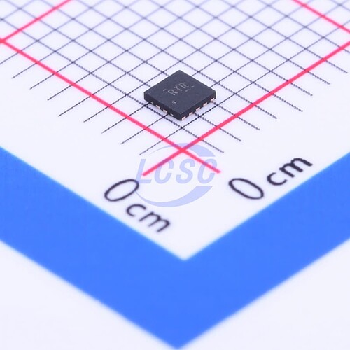
Meanwhile, this is a candidate, 4-line comparator, 5v, 2x2mm footprint.

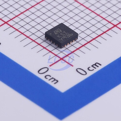
The other option witch does not require voltage dividers, but a little bigger 3x3mm.

I like the no-voltage divider one, up to 36v, a little bigger footprint but don’t need to futz around with resistors.

Cheers,
Valentine

1 Like