The board supports pwm-on and pwm-off BEMF detection. ST says the lines take time to stabilize, at low duty cycles measurements should be taken at the end of the pwm off phase. At high duty cycles measurements should be taken at the end of the pwm on phase. It might not be possible to do off-duty BEMF detection and current sensing at the same time (needs research).
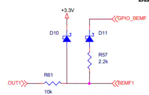
For on-pwm BEMF detection, GPIO_BEMF should be configured as output and driven low. The BEMF1 pin connected to the CPU can be read to obtain a measurement. How do I calculate gain from this circuit? Measurements suggest the gain should be around 40.
Is there an industry standard algorithm to detect the zero-crossings?
Essentially there seem to be two major ways to go: using ADCs or using comparators. On the B-G431B-ESC it looks like the BEMF pins are all on ADC2 but not on comparators, so I guess that choice has been made for you…
Coordinating the ADC measurements to the PWM is a bit complicated, but STM32 supports it.
My readings seem to have a good amount of noise. It looks like some kind of signal filtering would be helpful, but ST doesn’t explain this. I’m looking into kalman filters to model the system, and a python tool for model verification based on captured traces. Maybe I’m thinking too hard…
When sampling during pwn-off, the voltage falls outside the range of the ADC. This can be ‘fixed’ with FocMotor->modulation_centered = 0, but this means pwm-off is limited to ~12% duty cycle.
When sampling during pwm-on time, the ADC’s return 0 if the power supply voltage is less than approximately 20V. The exact threshold is influenced by temperature, my board can reliably detect the temperature fluctuations from forced airflow (read: blowing on the board). This board is designed for 6-cell lipo (~22v), Apparently this means BEMF detection doesn’t work with less than 6 cells. Or more than 6.
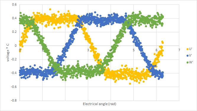
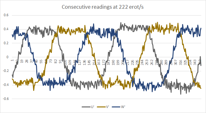
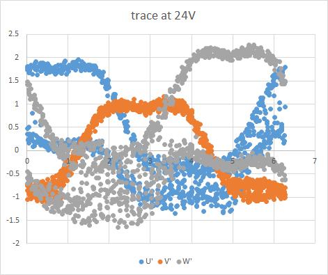
Here are some traces (pwm-on, 100rad/s) with various operating conditions.
The board works well on higher voltages, but only when cold.
The good news is that pwm-on sampling works well if an appropriate input voltage is selected, so we might not need pwm-off or expensive signal filtering.