I have a B-G431B-ESC1 and AS5047p encoder with a 350w hoverboard motor. I need get some inputs to ESC from external arduino and As5047p. These are,
ESC A+ / PB6 → A Phase from Encoder (INPUT / Default)
ESC B+ / PB7 → B Phase from Encoder (INPUT / Default)
ESC Z+ / PB8 → Reserved for triggering external mosfet for braking resistor (OUTPUT / NOT DEFAULT)
ESC PWM / PA15 → PWM Input from arduino for setting required Torque value (INPUT / NOT DEFAULT)
I Think, these are ok, if not please warn me.
Now I need one more IO pin for sending direction signal from Arduino to ESC. It is Low / High only.
As I can see from pinout scheme, I have available some pins which are used for different purposes.
ESC CAN TX / PB9
ESC CAN RX / PA11
ESC USART2_TX / PB3
ESC USART2_RX / PB4
If there is more IO pins (solderable) exist, please warn me again.
I prefer to use CAN_RX or CAN_TX pins, not USART2 pins, because I may need them later / programing.
So the question is, can I use these free IO pins as a regular IO pins on a MCU , or special configuration is need ?
Also using
– ESC Z+ / PB8 pin as OUTPUN pin for triggering a mosfet
– ESC PWM / PA15 as PWM input for torque values from Arduino
any config changes or other things needed for ABOVE pins ?
I am using arduino ide + stm32duino pack and Simplefoc for Closed Loop Torque control.
According to the schematics I can find for the B-G431-ESC1, and also its user-manual, the CAN_RX and CAN_TX are connected to a CAN transceiver, so I assume the solder pads are for CANH/CANL - not suitable for your purpose.
So I’d say using PB9/PA11 is a no-go, except for CAN.
The PWM on PA15 will work, but we don’t have a driver for this. You’ll have to write your own input routines, being careful not to busy-wait… ideally using the MCU’s timers to do it with little or no overhead.
Why not use this input for both speed and direction - just make 0 the middle point, and have a speed signal that can be negative or positive? Then you only need one input for speed and direction…
I can not find STM32HWEncoder class now. Can STM32HWEncoder class can take only 2 parameters ? I not using ESC Z+ / PB8
ESC Z+ / PB8 pin as OUTPUT pin for triggering a mosfet. Is this require any config changes / pin mapping or just pinmode (Output) is ok?
Can you clarify that how can I carry torque value and direction info in single pwm channel. I will write handling code async way by timers as you said.
Hmmm… from the point of view of the MCU, its just a matter of pinMode(output). But there are two issues:
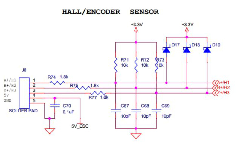
First, you have to check if all the filtering components attached to Z+ are a problem for you (see schematic below) in output mode.
Second, the MCU can only drive logic level FETs. So if you really want a FET for braking energy, you will need a driver for it, and the MCU can control the driver. But it’s only 3.3V and 20mA, so it can’t directly drive a power FET.
Well, if your PWM is 0-1024, then you can read the PWM value from your driver, and compute the direction/torque something like this:
int signed_pwm = pwm_value - 512
int torque = abs(signed_pwm)
if (signed_pwm>=0)
direction = 1; // forward
else
 direction = -1; // backward
I decided to try use Braking resistor with out mosfet. I am trying to design TVS diode based automatic braking circuit. So +Z will be free to use with encoder.
For torque and direction information, contacted with @Grizzly and he helped me about his CAN Bus implementation on B-G431B. ( Thank you @Grizzly )
So if possible, I will send torque, direction and more info to driver with Can Bus. I will try.
Do you think any problem with can bus comm. I mean speed, latency etc. ?
For most applications, I think it will work very well! The latency will maybe be higher than with a PWM-based protocol, but as we know it is quite possible to control robots etc via BlueTooth or WiFi, so it will also work via CAN.
Let us know how it goes, and good luck with your build!
I found this mosfet which can be drivable by 3.3 here. So I need to check voltage is above 12v to trigger mosfet. How can I read voltage for activating braking circuit ? Sorry for my to much questions, I am new to simplefoc and I am reading and learning without stopping.
Well, you need to design a circuit, then we can give some advice here…
Generally, the way to do it is to use a FET to pass excess energy through a shunt resistor to GND, and a circuit to compare the voltage and activate/deactivate the FET. Either to protect the PSU, or prevent overcharging a battery.
But this circuit could be a little complicated, if you’re not using the MCU to control the whole process, then you’ll need to find a comparator, voltage reference, and design a circuit around these, also adjusting all the voltages to the levels the components can handle. I was looking through my docs for a reference, but couldn’t find one just now.
So I decided to use external adc and voltage divider to measure voltage from arduino. Then when some over voltage, I will use mosfet to drive power resistors. Also I will use tvs diode for analogue backup system at higher voltage.
I will try can and pwm for communication. But I have 2 questions.
As I know pwm pin of esc is 5v tolerant. If I write pwm, say %50 duty cycle from arduino (5v), is esc will read that as %50 ? I think esc’s %50 is 1.65v (3.3v /2) and arduino’s is 2.5v(5v/2).
Can I use usb of esc as regular uart for serial.println for debug messages?
yes, you can! The USB is connected to USART2 on the STM32G431…
I think it will work - but not in the way you describe - its not an analog signal, its a PWM signal, which changes rapidly between 0V and VCC - which is 5V for the Arduino. You can think of it like a “square wave” signal. So the question is will the STM32 read the ardino signal low (0V) as low - yes. And will it read the high (5V) as high state? - yes. In the other direction (STM32 sending PWM to Arduino) it is not so clear it will work, but in this direction is should be ok.
Hi @etempm and @runger ,
Truly appreciate all the knowledge you guys are sharing here. Very grateful.
I’m also trying to use an AS5047 with B-G431B-ESC1. I however thought of using the PWM output of the AS5047 (I’m open to other options if any). For some reason, I can see the sensor working when using it in standalone mode (using the magnetic_sensor_pwm_example). However, it doesn’t help when using in closed loop. I’m including the initializing and setup code for the AS5047 connected as follows:
A+ → PWM(AS5047)
5V → Vin (AS5047)
GND → GND (AS5047)
BLDCDriver6PWM driver = BLDCDriver6PWM(A_PHASE_UH, A_PHASE_UL, A_PHASE_VH, A_PHASE_VL, A_PHASE_WH, A_PHASE_WL);
MagneticSensorPWM sensor = MagneticSensorPWM(A_HALL1, 4, 918);
void doPWM(){sensor.handlePWM();}
float target_angle = 0;
// instantiate the commander
Commander command = Commander(Serial);
void doTarget(char* cmd) { command.scalar(&target_angle, cmd); }

void setup() {


  // initialise magnetic sensor hardware
  sensor.init();
  sensor.enableInterrupt(doPWM);
  // link the motor to the sensor
  motor.linkSensor(&sensor);
I did use a AS5600 on I2C (connected to B+ and Z+ pins of B-G431B-ESC1) and it worked fine.
But not sure what I’m doing wrong with the AS5047. I feel like there’s something wrong about the way I’m doing my sensor initialization.
for reference the PWM info from AS5047 is as follows:
Further to my post, I tried MagneticSensorPWM sensor = MagneticSensorPWM(A_HALL1, 2, 918);
But I noticed Serial.println(sensor.getVelocity()); would always give me 0.0, even if Serial.print(sensor.getAngle()); would give me some values. But when I changed sensor.min_elapsed_time = 2.0; // 100us by default from 0.0001 it started giving me some values on the Serial.println(sensor.getVelocity());. It’s not reporting correct values though, as I see data fluctuating between positive and negative numbers randomly.
I am not sure what is wrong in your case, but a few comments:
The PWM sensor is our least accurate sensor type. It’s also very slow, giving at most one new value per 1ms. We really don’t recommend to use it you have another choice.
The values to the constructor are in milliseconds, not in “counts”. I’ve had the same confusion myself. So values like 4, 918 should be about correct in our experience.
This is way too high - the default value of 100us should be ok for most cases. This value is to ensure a minimum time between sensor readings when computing the velocity, otherwise the inaccuracies of the timestamp values returned by micros() can dominate the result.
For the PWM sensor you don’t have an issue with too quick sensor readings, because it is so slow to begin with.
This is strange. getVelocity() uses the values returned by getAngle(), so really it should not return 0 if there is some motion. Are you calling sensor.update()? If you’re calling motor.move() and motor.loopFOC() you don’t have to, but if you try to read the sensor without running the motor you have to add a sensor.update() to the loop…
mizzi, does your sensor have a direction pin? if you are going to revisit PWM you might want to make sure it is grounded or high, not floating. Also there is an example program to get the actual values of the PWM pulse.
I discovered a problem with the code base for PWM sensors, it does not appear to factor in the minimal pulse time when determine the raw count. For instance, if the minimal pulse time is 32 microseconds, which corresponds to zero angle, it does not subtract 32 microseconds from the pulse time before calculating the raw count for the data phase of the pulse. Thus, no matter how you set things it always has a sizeable dead spot at top dead center.