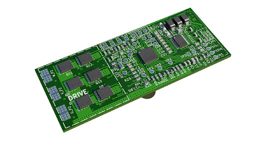
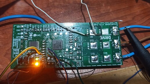
I have a custom board design based on B-G431B-ESC1. In my design i used MB1419 C-01 as a base schematic. Some board photos for those playing at home:
Here are my hardware changes:
- Built in ST-Link removed.
- CAN Support removed.
- Double (Parallel) mosfet config.NCEP40T11G chosed instead of STL180N6F7 mosfet.
- Aux power supply changed to LMR16006Y instead of L7986TR.
- 5v and 3.3v LDFPVR regulators are changed with AMS1117-X.X
- Gate Driver is changed to FD6288T (EG2133) instead of L6387ED.
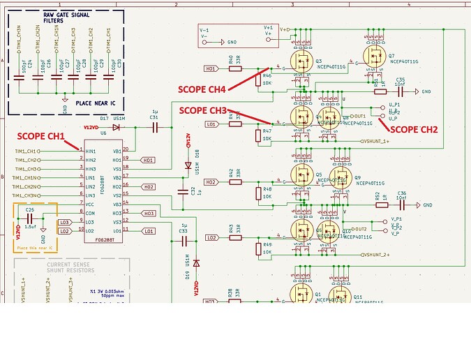
Rest of schematic is same as original MB1419 C-01 schematic. Here is my modified schematic.
My main goal was made it cheaper and more powerful ![]() however i believe i have issues with gate driver unfortunately.
however i believe i have issues with gate driver unfortunately.
Platformio config file:
[env:disco_b_g431b_esc1]
platform = ststm32
board = disco_b_g431b_esc1
framework = arduino
lib_deps = askuric/Simple FOC@^2.3.3
			SPI
			Wire
monitor_speed = 115200
lib_archive = false
build_flags =
	-DHAL_OPAMP_MODULE_ENABLED
	-D PIO_FRAMEWORK_ARDUINO_NANOLIB_FLOAT_PRINTF
	-D SIMPLEFOC_PWM_LOWSIDE_ACTIVE_HIGH=false
	-D SIMPLEFOC_STM32_DEBUG
My openloop code, please excuse hall sensor code garbage:
#include <SimpleFOC.h>
#include <Arduino.h>
// #define SIMPLEFOC_PWM_LOWSIDE_ACTIVE_HIGH false
HallSensor sensor = HallSensor(A_HALL3, A_HALL2, A_HALL1, 7);
BLDCMotor motor = BLDCMotor(7);
BLDCDriver6PWM driver = BLDCDriver6PWM(A_PHASE_UH, A_PHASE_UL, A_PHASE_VH, A_PHASE_VL, A_PHASE_WH, A_PHASE_WL);
LowsideCurrentSense currentSense = LowsideCurrentSense(0.005, -64.0/7.0, A_OP1_OUT, A_OP2_OUT, A_OP3_OUT);
// interrupt routine initialization
void doA(){sensor.handleA();}
void doB(){sensor.handleB();}
void doC(){sensor.handleC();}
float target = 20.0;
void serialLoop() {
static String recieved_chars;
while (Serial.available()) {
char inChar = (char) Serial.read();
recieved_chars += inChar;
if (inChar == '\n') {
target = recieved_chars.toFloat();
Serial.print("Target = "); Serial.println(target);
recieved_chars = "";
}
}
}
void setup() {
Serial.begin(115200);
delay(1000);
motor.useMonitoring(Serial);
// SimpleFOCDebug::enable(&Serial);
sensor.init();
// enable hall sensor hardware interrupts
sensor.enableInterrupts(doA, doB, doC);
driver.voltage_power_supply = 15;
driver.init();
motor.linkDriver(&driver);
motor.linkSensor(&sensor);
motor.voltage_limit = 1.7; // [V]
motor.velocity_limit = 300; // [rad/s]
motor.voltage_sensor_align = 1.5;
motor.controller = MotionControlType::velocity_openloop;
motor.init();
currentSense.linkDriver(&driver);
currentSense.init();
currentSense.skip_align = true;
motor.linkCurrentSense(¤tSense);
Serial.println("setup");
motor.initFOC();
}
void loop() {
serialLoop();
motor.loopFOC();
motor.move(target);
}
I have an original B-G431B-ESC1 and tested it on openloop code except “-D SIMPLEFOC_PWM_LOWSIDE_ACTIVE_HIGH=false” parameter in platformio.ini it works fine of course but it doesn’t work on my board.
According to this post EG2133 have inverted inputs? and i should use “-D SIMPLEFOC_PWM_LOWSIDE_ACTIVE_HIGH=false” parameter on platformio.ini. Thats why i modified software.
To investigate and solve this issue i connected scope to my ESC’s following points:
CH1 to U Phase High Side gate driver input
CH2 to U Phase Output to motor
CH3 to Q8 gate (Low Side)
CH4 to Q7 gate (High Side)
Above scope shot is taken without connecting to motor (U V W phases are floating.) and using EG2133 gate driver. Here is a video of event.
If i connect motor, it starts motor and motor tries to move but it doesn’t succeed. Here is a video to explain behavior.
Things are i tried so far:
- Checked 12v 5v and 3.3v power supplies. I even feeded them externally from bench power supplies. Result didn’t changed.
- Changed FD6288T gate driver with EG2133 result seems same.
- Tested with hall sensors and current sense, result seems same motor doesn’t turn.
- Checked my hardware design and i made another board just to be sure i didn’t make a mistake during PCB assembly. I hand assembled all of this stuff. 2 boards behave exactly.
- Checked V and W phases gate driver inputs, i can see pwm signal same as U phase.
- Changed EG2133 gate driver wıth a new one result is same.
Things i will try:
- Change driver to FD6288T. But i am not sure if its inputs inverted or not?
Any help will be appreciated.


