Hello everyone!
I need some assistance with running my BLDC motor in closed-loop mode. Here’s the configuration of the hardware I’m using:
- Driver: B-G431B-ESC1
- Motor: Tarot gopro brushless motor (12N14P)
- Encoder: AS5047U in encoder mode
- Power Supply: 12V
I’ve tested the encoder separately, and it works correctly, giving a value of 6.28 radians per full rotation. I also tested the motor in open-loop mode, and it runs smoothly, maintaining the set speed. I verified the encoder signal using a logic analyzer, and the encoder provides exactly 1000 pulses per revolution, without any noise.
The issue arises when I try to run the motor in closed-loop mode. Here’s what happens:
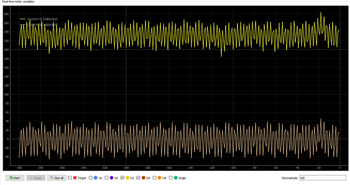
During the index search, the motor spins smoothly and correctly finds the zero position. However, after that, the motor refuses to rotate. I tried increasing the target using the M command, and while the current draw increases, the motor doesn’t move at all. In the console, I receive the following output:
Console output
TIM1-CH1 TIM1-CH1N TIM1-CH2 TIM1-CH2N TIM1-CH3 TIM1-CH3N score: 1
STM32-DRV: best: TIM1-CH1 TIM1-CH1N TIM1-CH2 TIM1-CH2N TIM1-CH3 TIM1-CH3N score: 1
STM32-DRV: Syncronising timers! Timer no. 1
STM32-DRV: Restarting timer 1
MOT: Monitor enabled!
MOT: Init
MOT: Enable driver.
MOT: Align sensor.
MOT: Index search...
MOT: Success!
MOT: sensor_direction==CCW
MOT: PP check: fail - estimated pp: 8.66
MOT: Zero elec. angle: 0.29
MOT: No current sense.
MOT: Ready.
Motor ready.
Set the target using serial terminal and command M:
PlatformIO configuration
[env:disco_b_g431b_esc2]
platform = ststm32
board = disco_b_g431b_esc1
framework = arduino
upload_protocol = stlink
monitor_speed = 115200
lib_archive = false
build_flags = -DHAL_OPAMP_MODULE_ENABLED
lib_deps =
  askuric/Simple FOC@^2.3.4
  SPI
  Wire
Source code
#include <SimpleFOC.h>

// BLDCMotor(pole pair number, phase resistance (optional) );
BLDCMotor motor = BLDCMotor(7);
// BLDCDriver6PWM(pwmAh, pwmAl, pwmBh, pwmBl, pwmCh, pwmCl, (en optional))
BLDCDriver6PWM driver = BLDCDriver6PWM(A_PHASE_UH, A_PHASE_UL, A_PHASE_VH, A_PHASE_VL, A_PHASE_WH, A_PHASE_WL);
Encoder encoder = Encoder(A_HALL1, A_HALL2, 1000, A_HALL3);
// interrupt routine initialisation
void doA(){encoder.handleA();}
void doB(){encoder.handleB();}
void doIndex(){encoder.handleIndex();}

// instantiate the commander
Commander command = Commander(Serial);
void doMotor(char* cmd) { command.motor(&motor, cmd); }

void setup() {

// use monitoring with serial
Serial.begin(115200);
// enable more verbose output for debugging
// comment out if not needed
SimpleFOCDebug::enable(&Serial);

// initialize encoder sensor hardware
encoder.init();
encoder.enableInterrupts(doA, doB, doIndex);
// link the motor to the sensor
motor.linkSensor(&encoder);

// driver config
// power supply voltage [V]
driver.voltage_power_supply = 12;
// driver init
if(!driver.init()){
  Serial.println("Driver init failed!");
  return;
}
// link driver
motor.linkDriver(&driver);

// aligning voltage
motor.voltage_sensor_align = 5;

// motor.sensor_direction = Direction::CW;

// set motion control loop to be used
motor.torque_controller = TorqueControlType::voltage;
motor.controller = MotionControlType::torque;

// comment out if not needed
motor.useMonitoring(Serial);

// initialize motor
if(!motor.init()){
  Serial.println("Motor init failed!");
  return;
}
// align sensor and start FOC
if(!motor.initFOC()){
  Serial.println("FOC init failed!");
  return;
}

// set the initial motor target
motor.target = 2; // Volts

// add target command M
command.add('M', doMotor, "Motor");

Serial.println(F("Motor ready."));
Serial.println(F("Set the target using serial terminal and command M:"));
_delay(1000);
}

void loop() {
// main FOC algorithm function
motor.loopFOC();

// Motion control function
motor.move();

// user communication
command.run();
}
Has anyone experienced a similar issue or have any ideas on how to resolve this?
Thank you in advance for your help!
