Hello to everyone, Im currently working on a project using hoverboard motors + b-g431b-esc1 drivers trying to run them on position control, right now i can read all the encoder positions from the hall sensor inside the motor and run the motor without problems on openloop velocity (Demonstration video: 15rad/s) mode. Im following the tuning guide from @Owen_Williams but when using torque (voltage control) mode or position the motor moves vibrating or if the target of voltage is below 8 then dont move or it makes impulses (in position mode it does impulses and when i change the angle it doesnt move), also its using about 18V 4A the initFOC() output is: (Just wondering if its a hardware (maybe psu voltage/current or code problem… I tried lowering the voltage from software voltage_limit to 1 or 2 and it vibrates less on the voltage mode)
Code used on velocity_openloop: (RIGHT) Code used on torque (voltage control) (LEFT) mode, apart from this code i tried angle position following SimpleFOC docs and Owen Williams guide
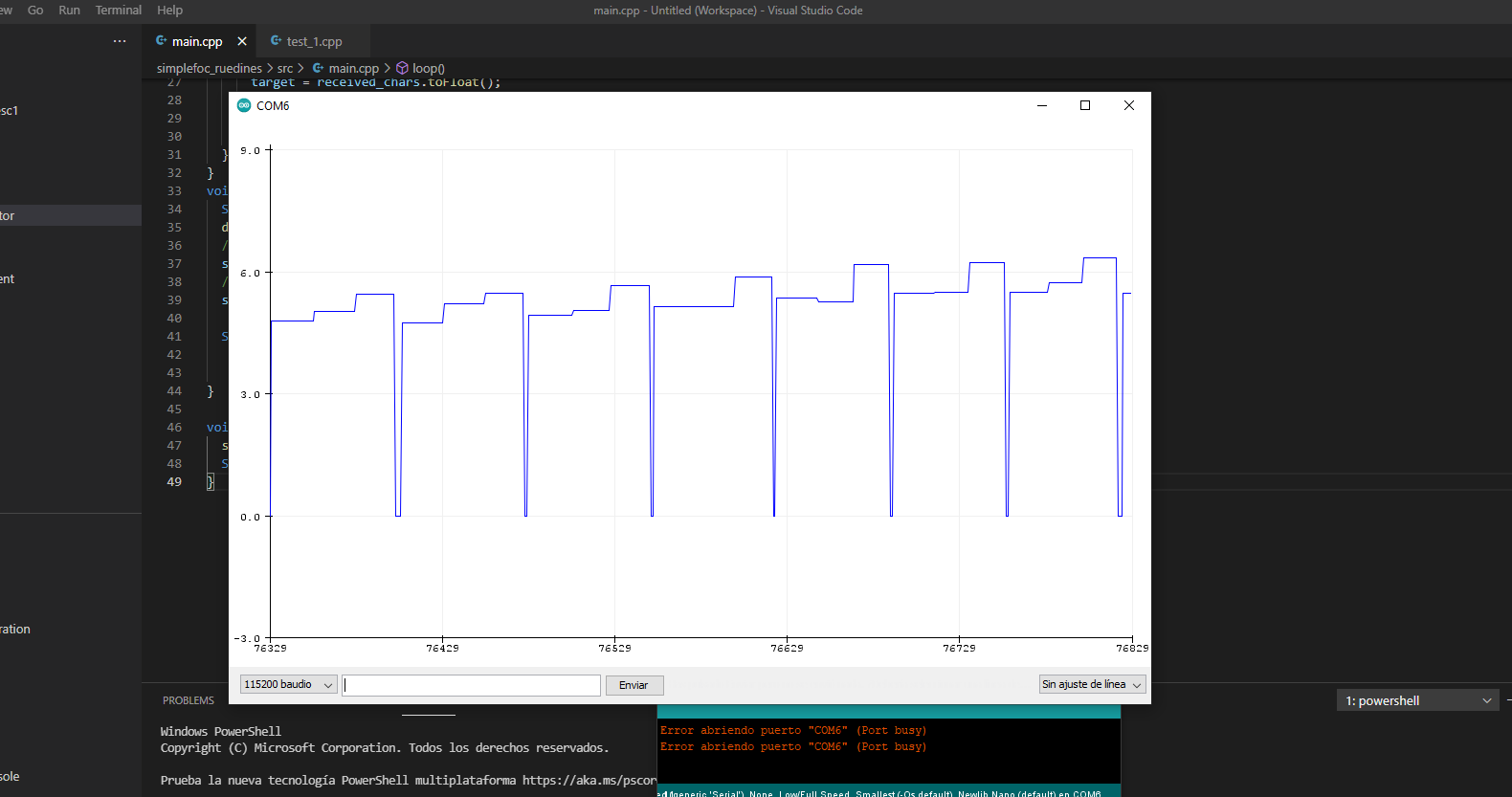
I add something that currently im watching that is the output from the velocity_openloop: with the encoder reading on the right then the velocity target and the velocity output from the encoder, as you can see the velocity from the encoder oscillates from 2 (the target) to 0, maybe thats the problem?
May I ask, if you decrease the frequency with which you measure the velocity, does the problem with the 0 entries go away? e.g. for example by setting motor.motion_downsample = 4
Another question: is the PP number right for your motor? You have configured 15, but looking at your output the PP check is failing and seems pretty certain about it being 10 pole-pairs. Does it work if you change the pole-pairs to 10?
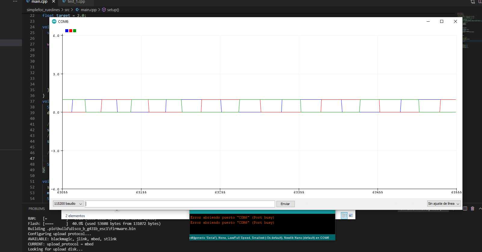
Only to clarify the motor moves at a good velocity constant and smooth so the problem comes from the sensor so i made another try moving the motor at 2 rad/s, and plotting the digital inputs from the hall pins 1,2,3: only to clarify, now i can see that its a hardware problem because the blue hall sensor its making some strange movements.
You might want to drop voltage_sensor_align to 1 to keep current low during initFOC
I’ve had lots of problems with pullups with the esc1.
The behaviour I typical see is:
With motor is unpowered - sensor readings are pretty good
with motor powered - sensor angle goes crazy
To debug can you print out sensor.total_interrupts in loop()? If you have hall pullup issues then you’ll see total_interrupts going to 1000+ in a few seconds. If you have pullup issues then you can fix it by shoving extra 2K resistors between hall a/b/c and 3.3/5v.
@runger - i don’t think downsampling works for hall sensors which are interrupt based.
@Owen_Williams The motor has 30 magnets so probably will be 15 pole pairs, I tried using another motor and another driver to verify if it was a hardware problem, i could solve the velocity problem now thats the output from sensor.get_velocity when moving the motor at 4/5 rad/s manually:
When running on velocity open loop 2rad/s, the first time i tried the openloop worked fine but now after trying the velocity closed loop and voltage closed loop im having the same issue :
So when going to velocity closed loop or open loop so when the drivers run the motor the velocity still have problems as you have tell me i tried printing the sensor.total_interrupts on velocity closed loop 2 rad/s and in a pair of seconds i have about 50000+. @runger the downsample doesn’t make any change. @Owen_Williams maybe should i think making what you teel me about the resistors if yes it would be awesome if you could give me more information about, i can see in your tutorials that you use the same drivers and you didn’t have problems with velocity. Also while debugging the digital read from the hall sensor i can see that the only sensor that have problems is the HALL1 (PB6) because on the other motor+driver it did the same on just the HALL1 (PB6) the HALL2 and 3 still being correct
I was wondering if maybe this function could help
// check if you need internal pullups
sensor.pullup = Pullup::USE_EXTERN;
I have another motor and driver but i dont think that the hardware have problems.
If you are seeing 50000+ interupts then you are definitely having pullup issues. Basically you should be getting 6 x 15 (pp) x speed (rad/s) interrupts per second. So at 5 rad/s you should be getting 450 interrupts per second. Anything higher are ‘ghost’ interrupts’ caused by the pullup not getting up towards 5v/3.3v properly.
I had pullup issues on this board and added 1 or 2K pullup resistors in addition to what the board provided. The USE_EXTERN vs USE_INTERN makes little difference - you might find use_intern to be a little better (it adds a small ~20K pullup resistor in chip) which is not enough - it needs a more powerful (lower resistance) pullup on each of the interrupt pins. On my board only a single hall had this problem - so it’s possible that you don’t need a pullup on each of the 3 hall wires. Experiment - you can even print out extra messages to work out which hall is contributing to that 50K interrups.
Adding 1K pullups can (probably) be done without soldering. I shove these resistors into the connector that joins the motor hall wire to the board hall wire. A bit dodgy but it works.
Hi Owen i tried soldering a 1k resistor in serie on the motor between the hallsensor output (a+) from the motor and the hallsensor input on the board (PB6) and the interrupts did improve a little bit (plotting the digitalread from every hallsensor). So then i tried putting two 1k resistor in series to achieve the 2k resitor but it did get worse. Photo from the 1k+1k resistors, maybe im not understanding what you are telling me about the place of placing the resitor but for now i dont get any improvement.
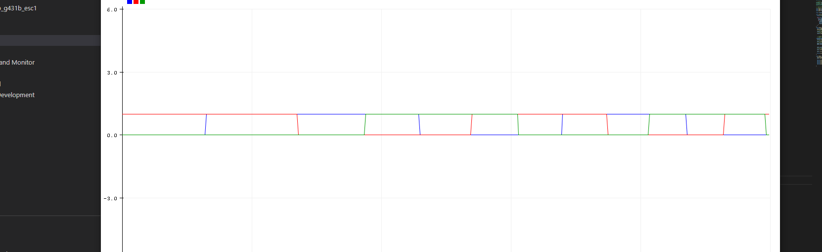
I also tried soldering 1k resistor on each hall output but still doing the same here you can see a plot of the digitalread of every hall at 2rad/s (if i increase the velocity to for example 12rad/s the interrupts get better but i think that its because the power consumption drops) :
You can see I’ve pushed two resistors as i had two twitchy interrupts. The resistor is between interrupt and 5/3.3v
I’m guessing you’ve soldered directly so can’t shove resistors into connector.
You might be able to go a bit lower than 1k although it’ll be leaking current.
The drivers are quite close to where the halls are soldered. I wondered whether my soldering or bad board design meant that they were interacting. I used a sweet wrapper to keep some distance between hall cable and chips.
Ok, now i can see that i was soldering the resistors bad, so today im gonna solder the resistors and let you know If everything is working fine.
Yes, the board have the hall pins too close but i did the soldering with a microscope to ensure that the pins are not touching. @erwin74 yes that was an option but knowing that Owen had this solution that works its better.
Now working perfectly i could solder the resistors inside the motor on the same pcb that come from the hall sensors, so everything is compact. Now lets go tuning!
Srry but just one little question .
Right now i have it tuned perfectly for position mode because it will be used on a quadruped legged robot, so i will run it using ROS from a jetson that outputs to the motors the next message [POSITION] + [VELOCITY] , right now the only way to change the velocity on the angle mode is using the velocity limit which is a little bit weird so i want to know if it will be possible send a velocity on each position command because the only way that im thinking right now to control this is send the position multiple times on “real time” that will let on a not smooth motor movement.
This is currently not possible in the library, but it shouldn’t be too hard to implement. I’ll make sure to comment this with the rest of the team and make sure we agree it’s worth implementing.
Ok David looking forward for the decision, @JorgeMaker yes that would be great but for now im good with position + velocity and also because torque depend on current sensing and with the b-g431b-esc1 its complex