Hey guys, I can’t really make head or tails of the above. Is it practical to read the current on the phases with the B-G431B-ESC1 board now? I have an idea that I think would work for sensorless commutation of a basic nature and would like to try it, but I need current sense. Like, not built into the library way in there, just to access it with analogread() or something? Can I do that? Like approximately how? There is all kinds of stuff about build flags and stuff. I mean in Arduino.
Yes, it is working now.
No, the current sensing setup for the B-G431 uses its internal op-amps, and needs its specific configuration. It can’t just work with standard Arduino analogRead().
Also, it uses a low-side sensing scheme, so you can only sense the current at specific times during the PWM. So you have to obtain the values via the LowSideCurrentSense class, which only works in conjunction with the SimpleFOC PWM drivers.
The B-G431 current sensing requires the opamp to be enabled in HAL. But I think if you are compiling for the board without getting errors then it should already be enabled.
If not, you have to add the build flag -DHAL_OPAMP_MODULE_ENABLED
I tried looking at the code, and I asked for example code, but the example code has everything woven into an attempt to actually drive the motor. I need to just access the current.
It appears that I could call getPhaseCurrents() as a method of the lowsidecurrent sensing class after doing the initialization stuff, but it returns some wacky object. I just want the current to go into a variable, doesn’t have to be zeroed. I can try to zero the ADC some other time.
I guess I could edit the source code of the library to get the getphasecurrents to put the info into a public variable and just access that after calling the function that updates the values? Pretty clunky of course.
I just want to use the current limiting for safety, mostly.
I am trying to get basic current sense working, just to start by printing out the values. Using Arduino.
I am getting the errors that seem to be due to the build flags not being set or something, as you predicted, Runger.
I have tried previously to set build flags in Arduino and it never seemed to work.
Does anyone know how to set the relevant build flags here?
I tried yet another motor driver chip today, and it failed. I need to implement my own driver. I have been able to get one working with a sensor but it is complicated and I fear it will be unreliable and expensive. I think I can implement a crude sensorless driver, and will share of course when I am done. But I need the current sensing to do that.
Here is the error output of Arduino:
Arduino: 1.8.16 (Windows 10), TD: 1.56, Board: "Discovery, B-G431B-ESC1, Mass Storage, Enabled (generic 'Serial'), None, Low/Full Speed, Smallest (-Os default), None, Newlib Nano (default)"

Warning: Board simplefoc:stm32:build doesn't define a 'build.board' preference. Auto-set to: STM32_BUILD

c:/users/user/appdata/local/arduino15/packages/stmicroelectronics/tools/xpack-arm-none-eabi-gcc/10.3.1-2.3/bin/../lib/gcc/arm-none-eabi/10.3.1/../../../../arm-none-eabi/bin/ld.exe: libraries\Simple_FOC\current_sense\hardware_specific\stm32\b_g431\b_g431_mcu.cpp.o: in function `_configureOPAMP(OPAMP_HandleTypeDef*, OPAMP_TypeDef*)':

b_g431_mcu.cpp:(.text._Z15_configureOPAMPP19OPAMP_HandleTypeDefP13OPAMP_TypeDef+0x22): undefined reference to `HAL_OPAMP_Init'

c:/users/user/appdata/local/arduino15/packages/stmicroelectronics/tools/xpack-arm-none-eabi-gcc/10.3.1-2.3/bin/../lib/gcc/arm-none-eabi/10.3.1/../../../../arm-none-eabi/bin/ld.exe: libraries\Simple_FOC\current_sense\hardware_specific\stm32\b_g431\b_g431_mcu.cpp.o: in function `_configureADCLowSide(void const*, int, int, int)':

b_g431_mcu.cpp:(.text._Z20_configureADCLowSidePKviii+0x6a): undefined reference to `HAL_OPAMP_Start'

c:/users/user/appdata/local/arduino15/packages/stmicroelectronics/tools/xpack-arm-none-eabi-gcc/10.3.1-2.3/bin/../lib/gcc/arm-none-eabi/10.3.1/../../../../arm-none-eabi/bin/ld.exe: b_g431_mcu.cpp:(.text._Z20_configureADCLowSidePKviii+0x70): undefined reference to `HAL_OPAMP_Start'

c:/users/user/appdata/local/arduino15/packages/stmicroelectronics/tools/xpack-arm-none-eabi-gcc/10.3.1-2.3/bin/../lib/gcc/arm-none-eabi/10.3.1/../../../../arm-none-eabi/bin/ld.exe: b_g431_mcu.cpp:(.text._Z20_configureADCLowSidePKviii+0x76): undefined reference to `HAL_OPAMP_Start'

collect2.exe: error: ld returned 1 exit status

exit status 1

Error compiling for board Discovery.


This report would have more information with
"Show verbose output during compilation"
option enabled in File -> Preferences.
this is the code I tried to compile:
#include <SimpleFOC.h>

// NUMBER OF POLE PAIRS, NOT POLES, specific to the motor being used!
BLDCMotor motor = BLDCMotor(7);
//this line must be changed for each board
BLDCDriver6PWM driver = BLDCDriver6PWM(A_PHASE_UH, A_PHASE_UL, A_PHASE_VH, A_PHASE_VL, A_PHASE_WH, A_PHASE_WL);
LowsideCurrentSense currentSense = LowsideCurrentSense(0.003, -64.0/7.0, A_OP1_OUT, A_OP2_OUT, A_OP3_OUT);
float goal_speed =0;
float v=2;
float v_diff=1;
int mode = 0;
float angle_for_angle_mode = 0;
float accel = 0.6;
float v_per_radsPS = 0.03;
float accel_v_boost = 0.5;
bool voltage_override = 1;
float A, B, C;
void SerialComm(){
  if (Serial.available() > 0){
  switch(Serial.peek()){
      case 't': Serial.read(); Serial.print("t"); Serial.println(goal_speed); break;
      case 'c': Serial.read(); Serial.print("c"); Serial.println(accel); break;
      case 'v': Serial.read(); Serial.print("v"); Serial.println(motor.voltage_limit); break;
      case 'p': Serial.read(); Serial.print("p"); Serial.println(v_per_radsPS, 4); break;
      case 'b': Serial.read(); Serial.print("b"); Serial.println(accel_v_boost); break;
      case 'o': Serial.read(); Serial.print("o"); Serial.println(voltage_override); break;
      case 's': Serial.read(); Serial.print("s"); Serial.println(motor.target); break;
      case 'e': Serial.read(); Serial.print("e"); if (motor.shaft_angle >= 0){
           Serial.println(motor.shaft_angle, 3);
           }
           if (motor.shaft_angle < 0){
           Serial.println((_2PI-(-1*motor.shaft_angle)), 3);
           }
           break;

       case 'w': Serial.read(); Serial.print("w"); Serial.println(driver.voltage_power_supply); break;

  case 'T': break;

  case 'C': break;

  case 'V':  break;

  case 'P':  break;

  case 'B':  break;

  case 'O':  break;

  case 'S': break;

  case 'A':  break;

  case 'M':  break;

  case 'W': ;break;

  default: Serial.read(); break; //if anything we don't recognize got in the buffer, clear it out or it will mess things up.

  }
}
  if (Serial.available() >= 9){
  switch(Serial.read())
  {
  case 'T': goal_speed = Serial.parseFloat();break;


  case 'C': accel = Serial.parseFloat();break;


  case 'V': v_diff = Serial.parseFloat(); break;


  case 'P': v_per_radsPS = Serial.parseFloat(); break;


  case 'B': accel_v_boost = Serial.parseFloat(); break;


  case 'O': voltage_override = Serial.parseFloat(); break;


  case 'S': motor.target = Serial.parseFloat();break;


  case 'A': angle_for_angle_mode = Serial.parseFloat(); break;

  case 'M': Serial.print("Mode_changed"); mode = int(Serial.parseFloat()); break;

  case 'W': driver.voltage_power_supply = Serial.parseFloat();break;


  //while(Serial.read() >= 0) ; //remove any extra stuff in the buffer after a single command was recieved, in case there are multiple commands in there.

  }
  }
}
void setup() {
  Serial.begin(1000000);
  Serial.println("test serial4");
  // driver config
  // power supply voltage [V]

  driver.voltage_power_supply = 24;
  driver.init();

  // link the motor and the driver
  motor.linkDriver(&driver);
  currentSense.linkDriver(&driver);
  currentSense.init();
  currentSense.skip_align = true;
  FOCModulationType::SinePWM;
  motor.voltage_limit = 3;   // [V]
  motor.velocity_limit = 320; // [rad/s]

  motor.controller = MotionControlType::velocity_openloop;

  // init motor hardware
  motor.init();
  motor.voltage_limit = 2;
  goal_speed = 2;
}

unsigned long int ticks_diff(unsigned long int t2,unsigned long int t1){ //t2 should be after t1, this is for calculating clock times.
  if (t2<t1){//t2 must have wrapped around after t1 was taken
     return (4294967295-(t1-t2));
  }
}
void loop() {
  switch(mode)
  {
  case 0:
  motor.controller = MotionControlType::velocity_openloop;
  for (int q = 0; q<10;q++){
   for(int j=0;j<5;j++){

     if (motor.target < goal_speed-(accel*1.5)){//commutation speed not positive enough
           if (motor.target < 0){//counterclockwise rotation, deaccelerating
      motor.target = motor.target+accel*0.7;
      motor.move();
      motor.voltage_limit = (v_diff+accel_v_boost+(pow(abs(motor.target),1.03)*v_per_radsPS))*voltage_override;
     }
          if (motor.target >= 0){ //clockwise rotation, accelerating
      motor.target = motor.target+accel;
      motor.move();
      motor.voltage_limit = (v_diff+accel_v_boost+(pow(abs(motor.target),1.03)*v_per_radsPS))*voltage_override;
     }
     }

     if (motor.target>=goal_speed-(accel*1.5)){//steady run phase
      if (motor.target<=goal_speed+(accel*1.5)){
        motor.move();
      motor.voltage_limit = (v_diff+(pow(abs(motor.target),1.03)*v_per_radsPS))*voltage_override; //constant run
      }
     }


     if (motor.target > goal_speed + (accel*1.5)){ //commutation speed too positive
           if (motor.target > 0){ //clockwise rotation, deaccelerating
      motor.target = motor.target-accel*0.7;
      motor.move();
      motor.voltage_limit = (v_diff+accel_v_boost+(pow(abs(motor.target),1.03)*v_per_radsPS))*voltage_override;
     }
          if (motor.target <= 0){
      motor.target = motor.target-accel; //counterclockwise rotation, accelerating
      motor.move();
      motor.voltage_limit = (v_diff+accel_v_boost+(pow(abs(motor.target),1.03)*v_per_radsPS))*voltage_override;
     }

     }
     for (int i=0;i<50;i++){ // shouldloop at about 37 khz on b-g431 board, appears to be only 5khz on lepton
     motor.move();
     motor.move();
     motor.move();
     motor.move();
     motor.move();
     }
     PhaseCurrent_s current1 = currentSense.getPhaseCurrents();
    A = current1.a;
    B = current1.b;
    C = current1.c;
    Serial.println(A);
     SerialComm();
}
 //Serial.println("t");

     /*if (abs(goal_speed) > motor.velocity_limit){
      if(goal_speed<0){
        goal_speed = motor.velocity_limit*(-1);
      }
      if(goal_speed>0){
      goal_speed = motor.velocity_limit;
      }
     }
     */
  }
  break;
  case 1:
    motor.controller = MotionControlType::angle_openloop;
  for (int w = 0 ; w < 10; w++){
      SerialComm();
      motor.move(angle_for_angle_mode);
      motor.voltage_limit = v;
  }

  break;
  }


}
Can anyone help? I think it will be useful to others too at some point.
edit:
Ok I was able to figure it out. in C:\Users\User\AppData\Local\Arduino15\packages\STMicroelectronics\hardware\stm32\2.4.0
There is a file, platform.txt
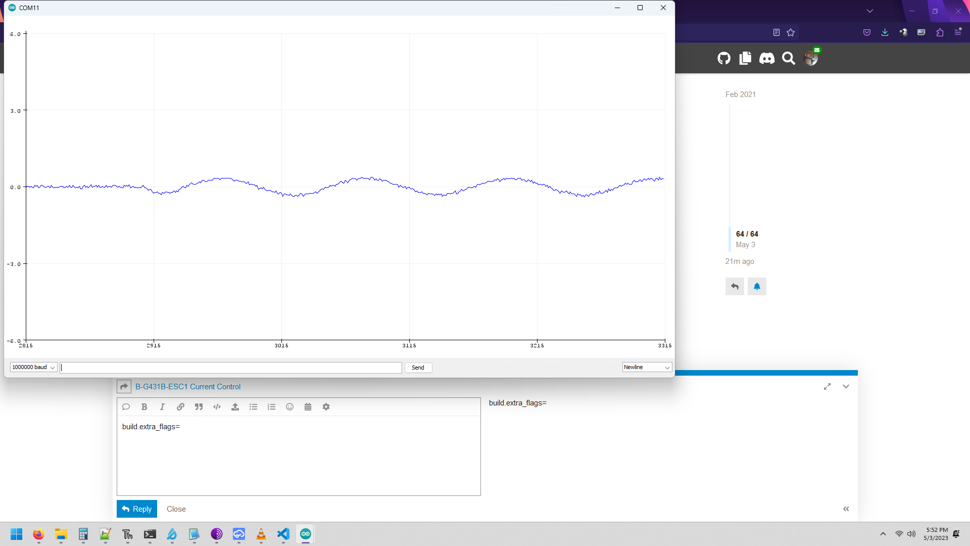
in that file, way down there is a line that says build.extra_flags=
If you add the string that Runger mentioned after the = symbol, everything works fine.
so, change the line to build.extra_flags=-DHAL_OPAMP_MODULE_ENABLED without the quotes.
Hi @scouttman
Thank you for going over your theory on the 64/7 gain value. This also matches with the 9.14 gain that ST uses in it’s workBench. Which is great!
I wasn’t able to understand how you got around the I1, I2 and I3 values here. I’m guessing it’s something to do with triggering the ADC in the middle of the PWM period. But not able to fully grasp your logic. If you have a moment to please elaborate.
Thank you so much.
I haven’t read the rest so this is a shot in the dark, but it might be something to do with that the current sensing is low side only. The current actually flowing through the sense resistor thus has to be sampled at a time that is synchronized with the PWM signal, or it will jump around a lot.
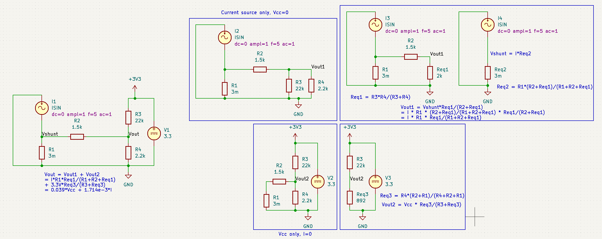
For anyone who’s curious on the I1,I2,I3. I believe this is how it’s derived:
Kirchoff’s current law , where current leaving a node is equal to all current entering the node.
If I1 is the current leaving the node (going to ST : Curr_fdbk1_OpAmp+)
I2 is the current coming from the 3.3V supply and I3 is the current coming from the Shunt, (Vshunt_1+).
I1 = I2+ I3
I1 is Vopamp/2.2k
I2 is (3.3 - Vopamp)/22k
I3 is (Vshunt - Vopamp)/2.2k
Hi,
I noticed this PR from you:
Did you see any difference with Simplefoc?
Hi, if you overclocked using the HSE it would lead to a wrong time base, otherwise no perceptible difference.