OK… SPI guide (not very beginner friendly ![]() )
)
Step 1: Finding free SPI
The stm32g431cb has 3 SPI ports (spi1/2/3).
I wanted to see if it was possible to expose one of them to hook up an as5047 SPI encoder.
What do we need? Well, as per some versions of its data sheet, the as5047 can run in two modes:
- Bidirectional mode (The one implemented in MagneticSensorSPI), using MOSI to set the register it’s reading, then MISO the read the value
- Unidirectional mode, when is enabled by tying MISO to VCC (3.3V in this case)
This means that in theory, all we need from the SPI port is SCK, and MISO. The CS pin can be done manually using any old GPIO, and MOSI in theory isn’t needed at all in this unidirectional mode.
Focusing first just on MISO and SCK in the stm32g431cb datasheet, and crossreferencing the pin allocation in um2516 (the B-G431B-ESC1 user manual):
- SPI1_SCK is PB3 (USART2_TX, so maybe) or PA5 (Curr_fdbk2_OPAmp-, so nope)
- SPI1_MISO is PA6 (OP2_OUT, nope), PB4 (USART2_RX, so maybe)
- SPI2_SCK is PB13 (NC, so that’s tough) or PF1 (OSC 8Mhz, nope), PF2 (not a pin in this package) PF9 (not a pin in this package)
- SPI2_MISO is PA10 (TIM1_CH3), PB14 (Temperature feedback)
- SPI3_SCK is PB3 (USART2_TX, so maybe) or PC10 (BUTTON… bingo!)
- SPI3_MISO is PB4 (USART2_RX, so maybe), PC11 (CAN_SHDN,TP2)
I face the choice: Sacrifice CAN+the button, which I’m not planning on using (by repurposing CAN_SHDN and the button input) for SPI3, or get rid of USART2, which I was planning on using for debugging unlocking either SPI1 or 3.
I decided that SPI3 via PC10/11 was the best choice.
Step 2: Soldering the B-G431B-ESC1 SPI wires
I loaded the board files from ST’s website onto the free Online PCB Viewer to Visualize and Share Electronics Design Projects | Altium 365 Viewer to look through the traces.
PC11 (our new SPI_MISO) is exposed on the bottom layer here (in dark blue):

The test point pad is the easiest target.
This brings us to our problem pin, PC10.
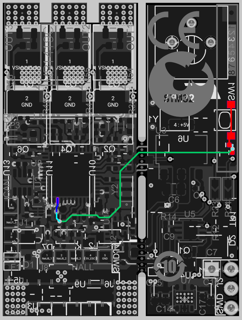
It’s only exposed in dark blue for a short little trace on the bottom layer, then it hides in the middle layers and wanders off the board. I could have tried just soldering to the side of the stlink board button (in red), but I plan to remove the STLink board at some point along this project, so I needed to try to solder to the bottom layer.
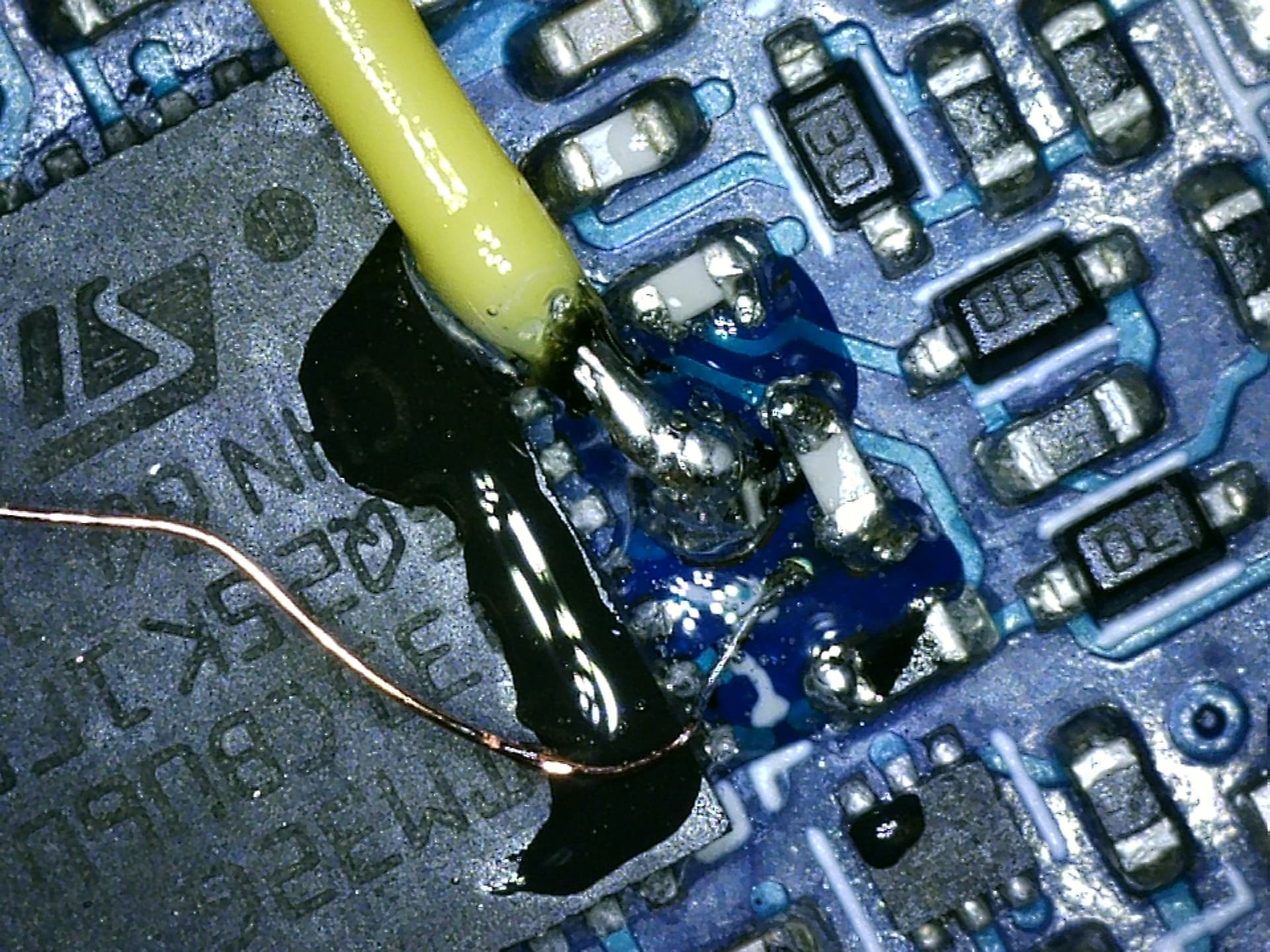
This is where things got dicey.
I used needle point tweezers to gently scrape the solder mask off above the via (viewing through a cheap USB microscope), then used (IPA scrub->flux->reapply solder) more or less in a loop 5-6 times until it worked and had a decent tin coating on both the TP2 pad, and the revealed via beside it, without any solder bridges.
Once things were tinned, applied pre-tinned the yellow 28 gauge wire to the test point (PA10), and the copper 38 gauge enameled wire to the tinned via. I then tested continuity with my multimeter (and microscope) to verify things seemed OK, and then coated the connections with a bit of clear epoxy.
Once the epoxy cured, I cut the magnet wire down to ~1cm, stripped it a bit, and soldered blue 28 gauge wire to it. I then heat-shrunk the blue and yellow wires together to provide strain relief.,
Before:

After:

The top side is much simpler:
- Purple wire: PWM for the SPI chip select pin (although basically any free pin would do)
- White wire: GND
- Red wire: 3.3V (borrowed from the 4 pin SWD header)

We now have all 5 wires needed for unidirectional SPI!
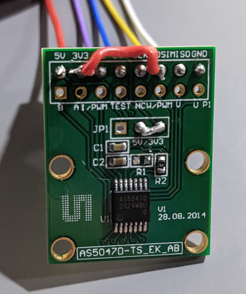
Step 3. Wiring up the AS5047
Back to nice 0.1" pitch stuff!
I wanted to run everything on 3.3V, which meant jumping the 5V and 3V3 pins in JP1 (why are there pre-populated headers on the wrong side!), so desoldered the headers with ceramic tweezers that made pulling the pins out super easy without wicking heat from them, and then re-soldered a bit of one of the pins as a jumper.
R1 needed to be moved to R2 as part of 3.3V mode (not sure why they have jumpers if you need to resolder resistors too…)
3V3 needed a jumper wire to MOSI to enable unidirectional mode on the AS5047 (red wire)
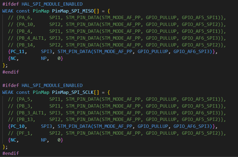
Step 4. Arduino Core Changes
You need to update C:\Users\ your_username \.platformio\packages\framework-arduinoststm32\variants\STM32G4xx\G431C(6-8-B)U_G441CBU\PeripheralPins_B_G431B_ESC1.c (or equivalent arduino location):
Step 5. PlatformIO Config
Only HAL_SPI_MODULE_ENABLED is super important here, but I’m including it all for completeness.
[env:disco_b_g431b_esc1]
platform = ststm32
board = disco_b_g431b_esc1
framework = arduino
monitor_speed = 115200
build_flags =
    -D PIO_FRAMEWORK_ARDUINO_NANOLIB_FLOAT_PRINTF
    -D HAL_OPAMP_MODULE_ENABLED
    -D HAL_TIM_MODULE_ENABLED
    -D HAL_SPI_MODULE_ENABLED
    -D PIO_FRAMEWORK_ARDUINO_ENABLE_CDC
lib_archive = false
lib_deps=
    askuric/Simple FOC @ ^2.0.2
    SPI
    Wire
Step 6. SPI Tribulations
At first, I hoped that MagneticSensorSPI would just work, and defined the normal arduino SPI3 definition, passing in parameters. I had toggled all the pins I wanted to use with digitalWrite, so I knew the wiring was correct, but this just didn’t work. It would hang waiting on an output buffer flag.
I ended up trying both the stm32 LL api, and the HAL, and getting it to work eventually with HAL.
It turns out that unidirectional mode flags and SPI_DIRECTION_2LINES_RXONLY are actually just a trap (the SPI clock just runs continuously and this causes the read to essentially give you your bytes with a random offset, or crashes the SPI device in some case. I’d call that a silicone bug, but… that’s just my opinion. Undesired bonus functionality maybe.
As a result, a lot of time was wasted between the default configuration hanging the processor and the most logical configuration producing garbage data.
In the end, simply telling the device to operate in bidirectional mode (which “lets” the SCK pin toggle as expected), with a stripped down HAL based SPI init+read seems to work fine.
Step 7. Working Code
#include <Arduino.h>
#include <SPI.h>
#include "pinconfig.h"
#include <SimpleFOC.h>

// Bringing online unidirectional SPI for AS5047 encoder
// 3.3V from the SWD pads
#define AS5047_SS PA15  // PWM pin, used as SPI CS pin, exposed on the pad 2nd from the VDC+ pad
#define PIN_SPI_MISO PC11  // CAN shdn isn't needed, SPI3_MISO. Exposed on TP2 pad by the STM32G micro silkscreen
#define PIN_SPI_SCK PC10   // the button, SPI3_SCK
#define PIN_SPI_MOSI NC  // No MOSI

// Todo: Add unidirectional mode support?
//MagneticSensorSPI sensor = MagneticSensorSPI(AS5047_SS, 14, 0x3FFF);

SPI_HandleTypeDef spi3_handle;
SPI_TypeDef *spi3;
void init_spi3(){
  // the following is mostly just a stripped down version of spi_com.c's spi_init
  spi3 = (SPI_TypeDef*)SPI3;
  spi3_handle.State = HAL_SPI_STATE_RESET;
  __HAL_RCC_SPI3_FORCE_RESET();

  //
    // 170Mhz / 16 ~= 10.625Mhz, which seems to work OK, despite being over 10
  spi3_handle.Init.BaudRatePrescaler = SPI_BAUDRATEPRESCALER_16;

  // no SSEL defined in the HAL
  spi3_handle.Init.NSS = SPI_NSS_SOFT;

  spi3_handle.Instance               = spi3;
  spi3_handle.Init.Mode              = SPI_MODE_MASTER;
  spi3_handle.Init.Direction         = SPI_DIRECTION_2LINES;  // we're only actually using one

  // SPI mode 1
  spi3_handle.Init.CLKPhase          = SPI_PHASE_2EDGE;
  spi3_handle.Init.CLKPolarity       = SPI_POLARITY_LOW;

  // more settings
  spi3_handle.Init.CRCCalculation    = SPI_CRCCALCULATION_DISABLE;
  spi3_handle.Init.CRCPolynomial     = 7;
  spi3_handle.Init.DataSize          = SPI_DATASIZE_16BIT;
  spi3_handle.Init.FirstBit          = SPI_FIRSTBIT_MSB;
  spi3_handle.Init.TIMode            = SPI_TIMODE_DISABLE;
  spi3_handle.Init.NSSPMode          = SPI_NSS_PULSE_DISABLE;

  // init pins
  pinmap_pinout(digitalPinToPinName(PIN_SPI_MISO), PinMap_SPI_MISO);
  pinmap_pinout(digitalPinToPinName(PIN_SPI_SCK), PinMap_SPI_SCLK);
  // from arduino spi_com.c
  uint32_t pull = (spi3_handle.Init.CLKPolarity == SPI_POLARITY_LOW) ? GPIO_PULLDOWN : GPIO_PULLUP;
  pin_PullConfig(get_GPIO_Port(STM_PORT(digitalPinToPinName(PIN_SPI_SCK))), STM_LL_GPIO_PIN(digitalPinToPinName(PIN_SPI_SCK)), pull);

  // enable SPI clock
  __HAL_RCC_SPI3_CLK_ENABLE();
  __HAL_RCC_SPI3_FORCE_RESET();
  __HAL_RCC_SPI3_RELEASE_RESET();

  // init HAL peripheral
  HAL_SPI_Init(&spi3_handle);
  __HAL_SPI_ENABLE(&spi3_handle);
}

void setup() {
  pinMode(LED_BUILTIN, OUTPUT);
  pinMode(AS5047_SS, OUTPUT);
  digitalWrite(AS5047_SS, HIGH);
  pinMode(AS5047_SS, OUTPUT);


  // init magnetic sensor
  //sensor.init(&SPI_3);
  Serial2.begin(115200);
  Serial2.println("Init Done");

  init_spi3();
}

uint16_t read_as5047() {


  digitalWrite(AS5047_SS, LOW); // SS low
  uint16_t value = 0;
  HAL_SPI_Receive(&spi3_handle, (uint8_t *)&value, 2, 1000);
  digitalWrite(AS5047_SS, HIGH);  // SS high

  // trim the extra 2 bits off the 14 bit value
	value = ( value ) & (0xFFFF >> 2);  // Return the data, stripping the non data (e.g parity) bits
  return value;
}

void loop() {
  digitalWrite(LED_BUILTIN, millis()%2000>1000);

  Serial2.println((float)read_as5047()/16384.0f*360.0f);
  delay(10);
}
Todo:
- Submit the SPI pin line change to the arduinostm32 repo.
- Solder up the power and phase leads and see if the ESC functionality still works!
TL;DR: IT WORKS

Recommendations:
- I’d strongly urge anyone considering doing this to look into just using the USART2_TX+USART2_RX (PB3/4) pins to do the same thing I did here. They’re broken out on that nice 0.1" pin header along with PWM which you can still use as CS. This does create a bit of a headache controlling the device, but CAN and SWD are still available, as well as maybe repurposing H1+H2 as USART1_TX/RX.
- ST, if you ever find your way to this post, just break out all the IOs on your dev boards!
- Chip Quick No clean flux in a syringe, and a $30-50 microscope if you don’t have them. There’s absolutely no reason why reworking 0402 components shouldn’t be easy! This is a more extreme example but with the right tools, you just need patience.
- Just try things! That via is 0.2-0.25mm diameter, and the trace is thinner. I’m glad I didn’t check before trying or I’d have said it couldn’t be done.
Update:
The SPI data was super noisy, which went away with a tweak (changing 8 bit to 16 bit SPI mode). I think something funky was going on between the two 8 bit halves, which is now gone. I also set the clock the DIV_16, which provides 10.64Mhz, vrs 128, which was 1.33Mhz.
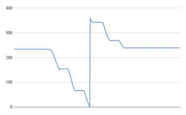
(spinning m motor unevenly by hand)
Update 2:
The sensor now is wrapped in a SimpleFOC Sensor class. Something might still be a bit fragile about the SPI code. Calling the angle read back to back seems to crash the CPU.
The project repo is now on github here: