Hi Guys. I have been working on my motorized overkill of Cyberpunk drone (Wyvern).
What im using:
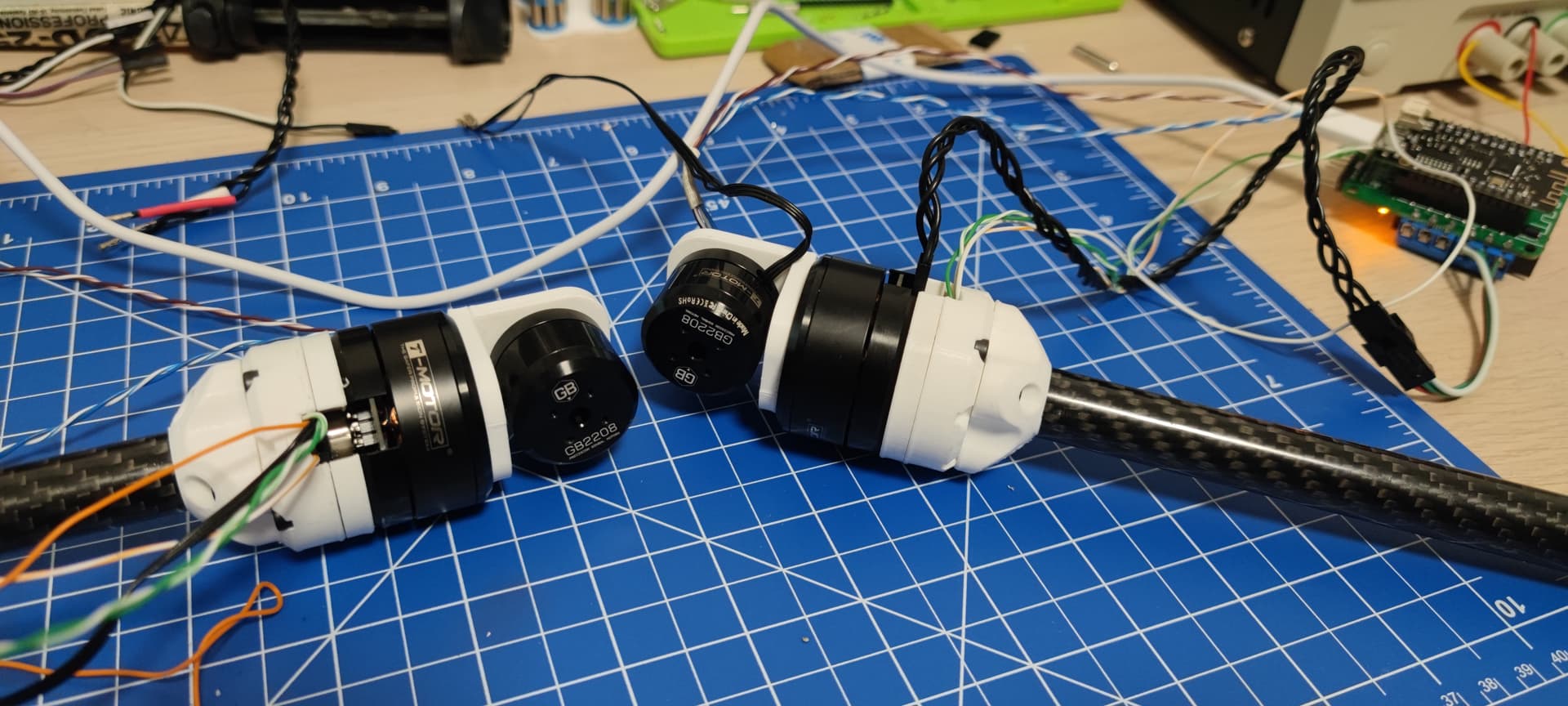
T-Motor GB2208 and T-Motor GB-36-1.
White board AS5600 (Operating on 5V on I2C for that extra gain)
ESP32 Dev
Deng Ge Dual L6432 Driverboard
Since AS5600 came with axial magnets i have ordered hollow magnets from germany which are diametrically magnetized.
Case scenario
Using GB2208 open-loop work fine, full rotation at 6.5 - at standard settings (def) with voltage limit 3v and velocity limit 10 operates very smoothly.
AS5600 gave me some trouble in the beginning but overally behave very well in magnetic sensor test
FOC is never able to pin point PP correctly, my motor has 7 pole pairs it sometimes guessing right, sometimes 7.6 sometimes 13…
Closed loop works very sporadically before it locks and i need to help motor with my fingers to get to the position but often it lost it and i need to reboot my program to make it work again
AS5600 has noisy velocity - usually stays at 0.00 when not moved but often jumps between -1.65 to 1.65 without any reason
AS5600 uses built in 10K pullups
DIR Connected to GND
Never was able to get Absolute zero on sensor in FOC angle position
Never was able to get proper calibration
Cogging test always shows some abstract deviation of -13K degrees
I use standerd PID settings
Tried with setting I and D to 0 and tuning P value to no avail
Tried tweak LPF to no success
Motor powered with 12 V and current limit 500ma.
Voltage limit set typically to 3V.
My assumption is that there is interference / jitter on AS5600 I2C side and FOC program looses calibration when the velocity goes wonky.
The AS5600 isn’t the best sensor to begin with, many users have problems with it. I2C is slow and will limit your performance compared to using a SPI based sensor.
10k is a bit high for the pull-ups, usually something like 2-5k works better.
But if the magnets are not the right ones, then all bets are off. Even if it seems to work when turning by hand, experience shows it will not work properly for FOC control with the wrong magnet.
Hmmmm… the GB2208 from T-motor should work no problem.
Maybe don’t try too many things at once… velocity mode (no torque control) is probably the easiest to tune, leave out current sensing for the beginning?
The ESP32 is a very fast MCU… really the I2C should be the limiting factor, but maybe check your loop iteration speed. With 400KHz I2C you should get more than 1kHz FOC loop iteration speed.
Which environment are you using to compile?
Which ESP32 is it? The newer S2s aren’t supported yet.
Definately looks like you’re having sensor problems the other aspects look great from the open loop control example.
On the one hand, it looks a bit like the sensor is losing track of the position, which happens with bad magnets, loose magnets, incorrect distance sensor to magnet etc… but it sounds like you have that under control.
Another thought is the PWM pin - is it just unconnected? If so I would recommend grounding it…
One thing that can lead to problems on initialization is if the voltage limit is too low - or if the motor is too heavily loaded. This can lead to the initialisation routine not being able to move the motor sufficiently to properly find the electrical zero.
Another thought: if you search in this forum for AS5600 there should be lots of threads!
On another note the 10K pull-ups seemed a bit odd to me but that’s what as5600 white board from aliexpress was delivered/assembled with, i don’t have any smd resisistors on hand at the moment.
I guess i could desolder these 10K ones and just shove in the 3.3K in wiring.
Though again i have pretty good angle readout on these factory 10K, again only thing that caught my attention was the jittery velocity readout on sensor test program.
Since i soldered cables instead of using the connectors the situation stabilized but its far from being even remotely satisfactory
I have noticed that when touching PGO (that’s the PWM pin right?) pin with my finger the jitter on velocity stabilizes somewhat, i will try to ground it and see how it goes.
Then again regarding magnets i got 3 different sizes all of them from german distributor they are diametrically magnetized of good quality.
Readout from AS5600 program is very good.
Magnet strenght is acceptable (not too weak not too strong)
The distance betwen magnet and sensor is approx 0.5mm (within specs).
Magnet is perfectly parrallel to the IC.
I think i have printed 6 revisions of motor / encoder holder so they are aligned perfectly.
I tried with 4 other encoder boards and issue prevail.
I will do as you suggest ground the PWM pin and swap the 10K pullups to 3.3K
I have tried to widdle with voltage limit, seem sweet spot is somewhere around 4.1v anything over draws too much current and 2208 heats up pretty significantly. Anything under 3v is pretty much unusable.
I will try power the driver with 24v and soft limit voltage to motor to something like 6. And see if there is any improvement, but im now really demotivated.
I have frankly went though almost every as5600 thread on the forum and considered every reply but they don’t apply to my case strangely so hence why i decided to reach out and see if with bit of knowledge sharing and trial and error sort this one out.
I have got 6 of each motors tons of other addons invested lots of time into this and i would really like to make it work
Hmm… no PGO is something for programming - pin 3, OUT, is the PWM/analog out pin. I believe there is a thread somewhere here in the forum about grounding it.
They recommend 4.7k in the datasheet for the pull-ups.
There are also some issues with powering it, I assume you’re using 5V power on the sensor since you’re using 5V I2C? It wants an extra capacitor in 5V mode - better check it’s on the sensor board.
I have figured it out and problem is more trivial than i initially anticipated.
In my motor and magnet assembly there were 2 irregularities:
first was fact that there was small notch that bearing clamp was gently rubbing against.
Another is taht the 3D printed circle was slightly oval.
After re-printing part wtih larger hole and depth that accomodate for bearing clamp i get PP check OK and electric angle is 0.17 constant… never reaches absolute zero i need to tweak it then.
Conclusion is that my encoder and program was good, it was just assembly issue.
Case closed class dismiss
The Zero electrical angle value printed out but he motor angle alignment does not have to be zero - it is the angle at which the zero electrical angle was found compared to the shaft angle.