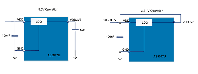
Hi Guys,
I am trying to use the AS5047U magnetic encoder in incremental mode with a CubeMars GL40 motor and an Odrive 3.6 to do FOC control. I know the encoder spreadsheet indicates that these are not supported, but surely that refers to non-incremental data acquisition modes? I can’t see why this chip’s incremental interface would be different from others, but I am a novice with electronics.
The encoder is mounted on the rear of the motor. The magnet is as close to the chip centre as possible with a Z spacing of ~0.5mm. Here are some screengrabs to get an idea of the setup.
Right now, the encoder is giving no response at all in incremental mode or SPI mode. I have attached probes from an oscilloscope to the appropriate pins to inspect both of these modes of operation. 0V with respect to GND is reported on the A/B/I lines with rotation of the motor. This remains true when I try to wave a magnet across the encoder to induce any noise signal.
I have also tried communicating with the device over SPI, using an Arduino as a master. I have attached probes to the SPI lines as well, and they report no signal on the MISO line. The code for communicating with the SPI bus is below.
#include <SPI.h>

const int cs = 10;
const int clk = 13;
const int mosi = 11;
const int miso = 12;

#define DATA_MASK         0x3FFF

#define OP_WRITE 0x0000
#define OP_READ  0x4000

#define PARITY_EVEN 0x0000
#define PARITY_ODD  0x8000

#define ADDR_NOP          0x0000
#define ADDR_ERRFL        0x0001
#define ADDR_PROG         0x0003
#define ADDR_DIAAGC       0x3FFC
#define ADDR_MAG          0x3FFD
#define ADDR_ANGLEUNC     0x3FFE
#define ADDR_ANGLECOM     0x3FFF
#define ADDR_SETTINGS1    0x0018
#define ADDR_SETTINGS2    0x0019

#define CMD_R_NOP       (OP_READ | ADDR_NOP)
#define CMD_R_ERRFL     (OP_READ | ADDR_ERRFL)
#define CMD_R_PROG      (OP_READ | ADDR_PROG)
#define CMD_R_DIAAGC    (OP_READ | ADDR_DIAAGC)
#define CMD_R_MAG       (OP_READ | ADDR_MAG)
#define CMD_R_ANGLEUNC  (OP_READ | ADDR_ANGLEUNC)
#define CMD_R_ANGLECOM  (OP_READ | ADDR_ANGLECOM)
#define CMD_R_SETTINGS1 (OP_READ | ADDR_SETTINGS1)
#define CMD_R_SETTINGS2 (OP_READ | ADDR_SETTINGS2)

int16_t AS5047_Read(int ic_cs, uint16_t command){

  int16_t res = 0;
  // First frame of SPI - send a 16 bit command
  digitalWrite(ic_cs, LOW);
  SPI.transfer16(command);
  digitalWrite(ic_cs, HIGH);

  // Second frame of SPI - read the result of the command
  digitalWrite(ic_cs, LOW);
  res = SPI.transfer16(CMD_R_NOP);
  digitalWrite(ic_cs, HIGH);

  // Mask off unused bits
  res &= DATA_MASK;

  return res;
}


void setup() {
  // put your setup code here, to run once:
  Serial.begin(9600);
  pinMode(cs,OUTPUT);

   SPI.beginTransaction(SPISettings(
       100000, MSBFIRST,
       SPI_MODE1)); // Configure SPI for this transaction and begin transaction

}

void loop() {
  // put your main code here, to run repeatedly:
  int16_t masked_data = AS5047_Read(cs, CMD_R_SETTINGS1);
  Serial.println(masked_data);

  delay(10);

}
I have included my schematic below as a reference in case I have done something completely wrong. I have included some notes about the modifications and debugging I attempted.
Any help would be greatly appreciated.


