Progress - ISH…
I went back to basics, and found the below code, where I modified the motor.target based on 6.28 being 1 Revolution per second, and adjusted to get close to 33.3RPM and 45RPM.
I’ve left out the button stuff, for now - I just wanted to get the motor moving.
The only issue I have here (until I start adding bits) is the consistency of movement.
it fluctuates around 33.3 and 45, but with slight dips and spikes (more than with the FOC Shield and Uno.
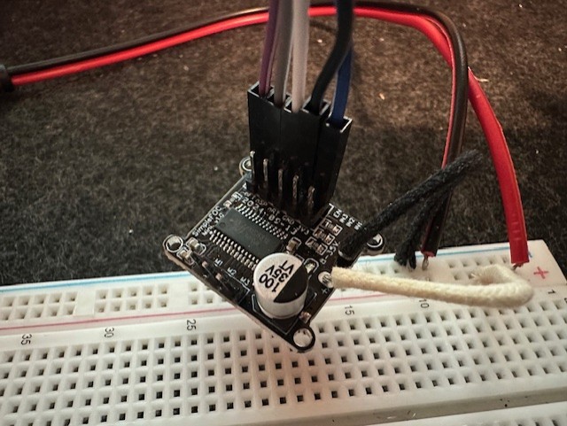
So - My question for right now, is - is this due to the code and fluctuations the voltage as indicated by me, or is that more likely to be from poor voltage / current supplied by my FOC Mini, which I suspect to be a clone (Amazon UK Purchase).
Is this something that the proper FOC mini would solve, or is the issue still in the code (or a combination)?
side Question - The official page says out of stock on the thumbnails for the SimpleFOC boards, but the main page shows an order button. Are they available officially, or is the shop no longer an official channel? I can buy from AliExpress, but if the board i have is the issue, I have no guarantee that the one I get from somewhere else would be made using bettr components.
#include <SimpleFOC.h>

// BLDCMotor(pole pair number, phase resistance (optional) );
BLDCMotor motor = BLDCMotor(11);
// BLDCDriver3PWM(pwmA, pwmB, pwmC, Enable(optional));
BLDCDriver3PWM driver = BLDCDriver3PWM(9, 5, 6, 8);

// instantiate the commander
Commander command = Commander(Serial);
void doTarget(char* cmd) { command.scalar(&motor.target, cmd); }
void doLimit(char* cmd) { command.scalar(&motor.voltage_limit, cmd); }

void setup() {

  // use monitoring with serial
  Serial.begin(115200);
  // enable more verbose output for debugging
  // comment out if not needed
  SimpleFOCDebug::enable(&Serial);

  // driver config
  // power supply voltage [V]
  driver.voltage_power_supply = 12;
  // limit the maximal dc voltage the driver can set
  // as a protection measure for the low-resistance motors
  // this value is fixed on startup
  driver.voltage_limit = 6;
  if(!driver.init()){
    Serial.println("Driver init failed!");
    return;
  }
  // link the motor and the driver
  motor.linkDriver(&driver);

  // limiting motor movements
  // limit the voltage to be set to the motor
  // start very low for high resistance motors
  // current = voltage / resistance, so try to be well under 1Amp
  motor.voltage_limit = 12;   // [V]

  // open loop control config
  motor.controller = MotionControlType::velocity_openloop;

  // init motor hardware
  if(!motor.init()){
    Serial.println("Motor init failed!");
    return;
  }

  // set the target velocity [rad/s]
  //motor.target = 3.48; // 33.3RPM
  motor.target = 4.71; // 45RPM

  // add target command T
  command.add('T', doTarget, "target velocity");
  command.add('L', doLimit, "voltage limit");

  Serial.println("Motor ready!");
  Serial.println("Set target velocity [rad/s]");
  _delay(1000);
}

void loop() {

  // open loop velocity movement
  motor.move();

  // user communication
  command.run();
}


Oh - I thought that's how they were designed to work anyway - the shield I mean. I have the wall plug connected to the shield, where the shield must be passing through power to the Uno, as i don't have it connected via USB or DC barrel directly to the Uno. I'm assumiing it's just passing through 5V, as the shield connects to all pins on both sides of the Uno https://imgur.com/a/UyVNrxq While this is a large motor, It's only set to turn at 33.3 and 45 RPM, so nothing crazy. I will have a look into th ebuck converter approach and see what I learn. Thank you for your replies!
– outsidethenineAh, the video makes things so much clearer, seems to be working really good. I was assuming you have the Simple FOC Mini shield https://simplefoc.com/simplefoc_mini_product_v1 , hence the confusion. In any case, looking at the shield you are using, it has full length exposed pins coming down below the board, correct? So most of the height contribution is coming from the shield itself, the UNO is probably not adding a lot. Even if you replace the Uno with a Nano and connect it with wires, I doubt the height will reduce a lot.
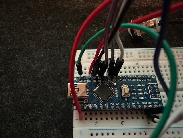
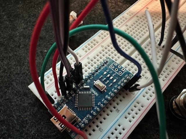
– motormakerI do have a SimpleFOC mini that I would like to use, but the current setup is just the shield. If I were to use an Arduino Nano and a SimpleFOC Mini, i could solder directly to the board and have them side by side, rather than stacked. The Uno has a large USB connector and DC Barrel connector, as well as those large female pin connectors. I'll look into using buck converter and trying to take a single power supply to both boards. The DC/USB plug was a good suggestion, but feels like a workaround, rather than me learning how to do something properly. Thanks for your help - it's appreciated!
– outsidethenine