Whilst this might be possible, it probably isn’t sensible. Lets say you use TIM1, TIM2, TIM3, TIM4 for each BLDC as in diagram below:
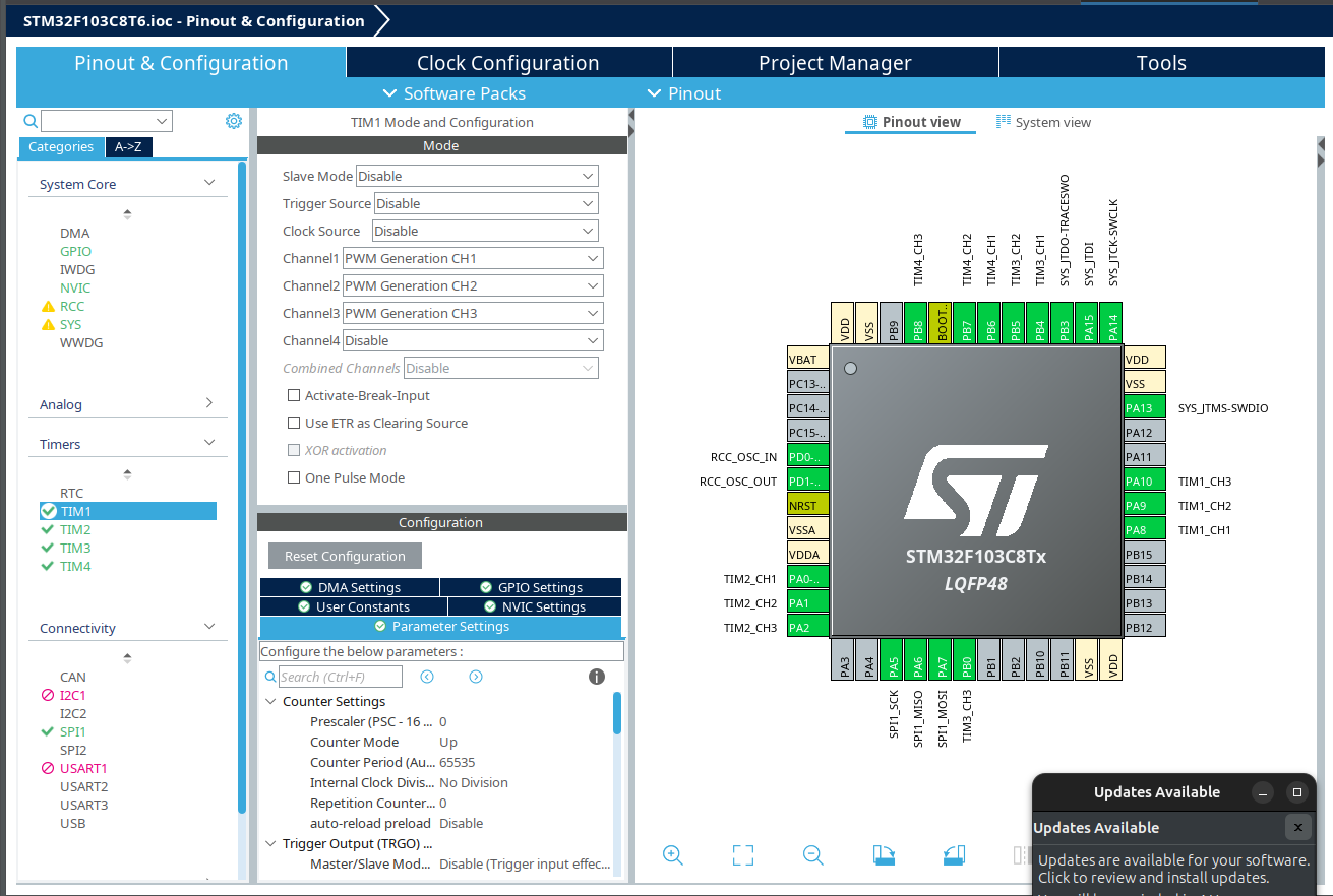
There aren’t many pins left. There is a conflict on stlink (might be able to program it through usb or usart). But more importantly this chip is 72Mhz and it won’t want to be doing 4x FOC Maths calculations. If you add in sensors (for closed) loop for each bldc e.g spi with 4 separate chip selects - that will use up more cycles.
The black pill (STM32F411) is a bit faster at 100Mhz, but connecting 4x bldc is still not something I’d recommend. I might entertain doing 2x bldc on a black pill but would generally I’d prefer one mcu per motor with canbus to something else doing ‘the thinking’.
Perhaps I’m being too cautious, if the requirements were right (simple), a blue pill could work with 4x BLDC.