While reading hardware supported section I came across following:
STM32 devices
Stm32 devices are probably the best choice for the FOC implementation MCU. They are very powerful and have many external interrupt pins. They don’t loose too much performance due to counting and have much lower loop times making the FOC algorithm much smoother. Stm32 Bluepill can run up to 4 BLDC motors without a problem and Nucleo-64 can run 6+.

The biggest problem of using the STM32 boards in the community is the complexity of programming these devices. But since they have been integrated into the Arduino IDE even this is not a problem any more. Arduino SimpleFOClibrary code for stm32 devices is exactly the same as for Arduino UNO except the different pin numbers. Therefore I strongly urge you to consider using these devices in your projects because the results are awesome. 😃

Arduino SimpleFOCShield is completely compatible with Nucleo-64 devices. And from the shield version 1.3.1 you will be able to stack 2 of the shields with the Nucleo boards as well.
If I understood correctly blue pill can run 4 BLDC motors. Is it run simultaneously?
If so, can any one post reference design or pinouts please?
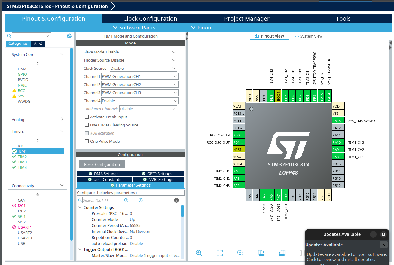
There aren’t many pins left. There is a conflict on stlink (might be able to program it through usb or usart). But more importantly this chip is 72Mhz and it won’t want to be doing 4x FOC Maths calculations. If you add in sensors (for closed) loop for each bldc e.g spi with 4 separate chip selects - that will use up more cycles.
The black pill (STM32F411) is a bit faster at 100Mhz, but connecting 4x bldc is still not something I’d recommend. I might entertain doing 2x bldc on a black pill but would generally I’d prefer one mcu per motor with canbus to something else doing ‘the thinking’.
Perhaps I’m being too cautious, if the requirements were right (simple), a blue pill could work with 4x BLDC.
@Owen_Williams Thank you for your quick response and pinout for STM32F103.
My goal is to demonstrate capacity of minimal low cost and simple hardware design to high school students. I will have ESP32-CAM on board for video and communication for motors control. Unfortunately ESP-CAM has only 2 gpios to spare.
If not STM32F01 please suggest any other MCU capable of doing 4 motors from 1 board.
The use case is for educational robot platform which will use 2 motors for moving the platform. and two motors to control pan/tilt platform on top of moving platform which have to carry weight of about 4 KG (solar panel, camera and rather large antenna system. So 2 driving wheel could be open loop and pan/tilt require angle mode I guess.Is it considered simple?
That 4Kgs sounds like quite a weight to tilt. Only the biggest gimbal motors (£100 each) would be able to handle that. Or you are looking at smaller motors with gearing to get required torque. You’ve got to chose some drivers/mosfets too. So yes, sounds reasonably complicated.
You could run everything openloop and put a mpu6050 on the thing tilting, but the motors might run hot.
For mosfet gate drivers I am planning to use 4 of these :
Solar and battery charging will be at 24V. So motor voltages at max would be 24V.
I have extensive experience in long range (in KMs even for 2.4 ghz band) antenna design, solar trackers, long range video transmission etc. So I can say all of these is simple for me. I have written code for solar tracker which is suitable for date, time and location based precise movements of motors without requiring mpu6050 here: GitHub - happytm/SunTracker: Sun Tracker using ESP32
What I lack in understanding is mosfets, gate drivers and SimpleFOC software in detail.So it is complicated for me. If you notice I am choosing parts based on it’s low cost because it is low budget project so even if it doe not work in terms of motor control it is only $10 in parts and lot of valuable learning.
Are you sure you couldn’t handle your motion system using stepper motors? Doing 4 motors with standard stepper drivers will be substantially easier, both computationally as well as hardware design. Plus, these types of parts are pretty easily available and you can buy low cost off the shelf drivers for them and control them easily even with bottom-tier hardware like F0 family.
The nema 17 stepper motor is the obvious choice, the one you find in most 3d printers. They are driven by drv8825 (or older a4988). They have a very simple step/dir interface which offers 1.8degrees per step (or better if you use microstepping).
If you know anyone with broken 3d printers you can probably salvage, but new parts are cheap. 4 motors and drivers would probably total $60. They require no sensor instead they assume that you have adjusted the current to ensure the motor never ‘slips a pole pair’.
They typically use a click switches to home the position of each motor.
If you want to continue to explore simplefoc then you could replace the step/dir driver with something like an l298n (more complex/more learning).
Steppers are harder to control than bldc using foc because they have more pole pairs (typically 50) requiring more resolution on sensors to measure each pp electrical revolution.
Stepper motors consume a lot of energy even when they don’t move. disabling the driver is risky, they can loose position.
I’d go for an oldfashioned hobby servo gimbal instead. They might not be as accurate, but they drop down to standby current at standstill.
I believe a dual-core ESP32 (such as the ESP32-WROOM-32) can drive 4 BLDC motors in closed-loop. Of course it’s more expensive than a Blue Pill, but not by far. See here for a well known brand with support, but you can find clones for half the price.
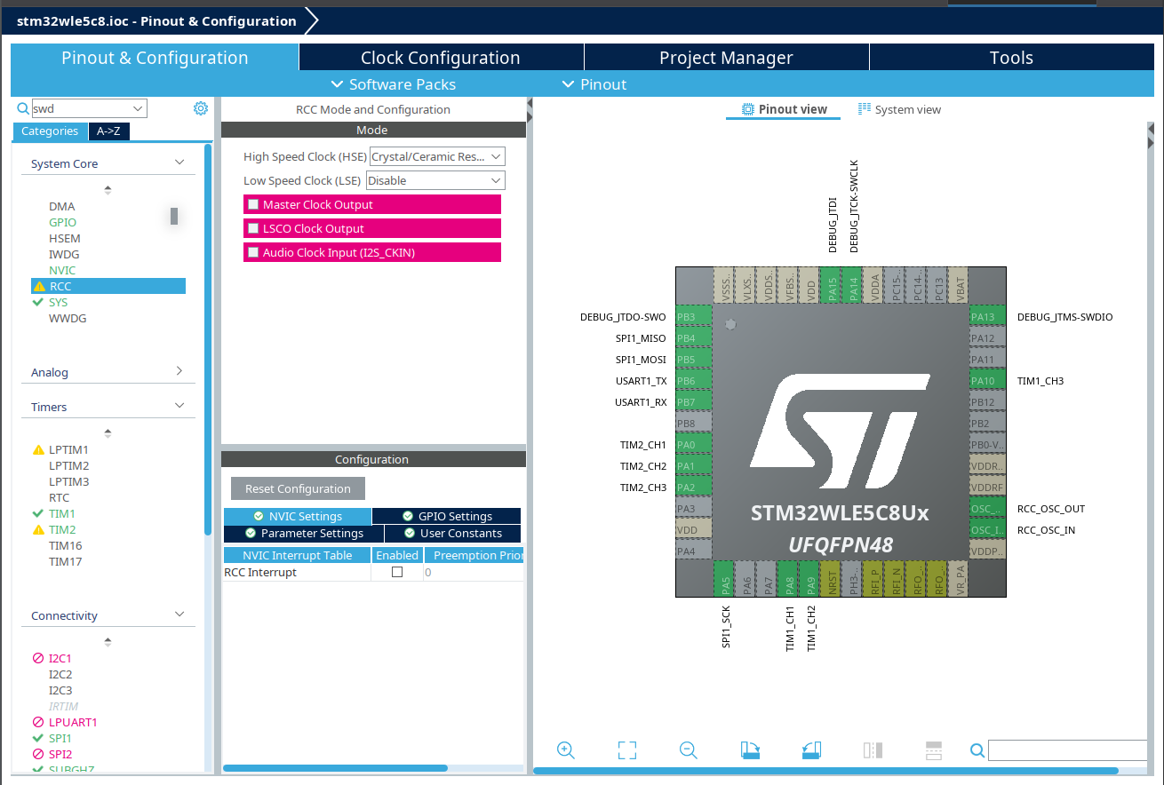
Any reason why the stm32wle5? It looks like it is a specialist low powered mcu aimed at LORA/radio comms. Not particularly fast (48Mhz). Only one of the timers says it can do 4 channel PWM - so I suspect this is not suitable.
A very popular stm32 cpu here is the stm32g431 - 170Mhz aimed at motor control. More expensive though.
stm32f1 = ok
stm32f4 = good
stm32g4 = better ← this is a good all rounder and costs ~$5
stm32h7 = best
stm32L (low powered)
stm32W (weird connectivity e.g. lora, bluetooth)
Regarding esp32, the literature generally says you can use any pins for PWM but the fine print says that some of the higher pins can only do input.
Total=23 pins, on which 22 are output and only 1 (SPI MISO) is input.
An ESP32 has 25 GPIO pins, but unfortunately 4 of them are input only. So you’re short of 1 output pin.
The solution is to get rid of the motor EN pins, by setting them to HIGH (you can also join them all together to the same pin). This will save you 4 pins, and you’re now good to go.
Issues you can expect down the road:
Among the 25 GPIO pins of the ESP32, 6 are strapping pins, i.e. with special behaviors. You’ll need to take care of those.
Ignoring the EN pins requires some caution, see here.
One ESP32 core is far than enough for 2 motors, but 4 motors might require the two cores. This will require a few lines of platform specific coding.
@Owen_Williams I brought up STM32WL because I watched video https://www.youtube.com/watch?v=V9NYwp4vAHI which show impressive power management of this chip. Plus built in LoRa can be used to control motors long range and thereby I can test my long range antenna system limits sitting in my chair. I already have few STM32WL modules (E77) from EByte. If I can use even 2 motors per micro controller that would be OK.
@quentin Wow! Thank you for detailed response including problems I can run into. It looks promising though.
What if I use 2 encoders only for pan/tilt platform and run motors for moving platform in open loop without encoders thereby saving 2 CS pins and using all EN pins.
I still have to figure out strapping pins you warned me about.
Thanks.
On the stm32wle5c8 pins.
TIM1 is an advanced timer supports 6PWM or 3PWM. TIM2 supports 3PWM only. The other timers are not capable of multi channel PWM. So it might be possible to do 2x BLDC
I’m not an expert on stm32 config so do your own checks. Personally, I’d probably go the esp32 route, maybe the wifi or ble might be a substitute for the lora
Just to chime in from some experience here: trying to run multiple motors on any MCU is a challenge. If you can avoid it by choosing an architecture where each motor gets its own MCU, it will be much easier for you.
The others have already discussed the problems regarding pin assignments. You have to keep in mind that for a real-world solution you typically need many more pins than just 3 for PWM. Each motor needs a sensor, and drivers normally have enable and fault signals. You need pins for control input and user feedback. Depending on the MCU, all these different functions may be in conflict with each other. Having enough pins for 4 motors + sensors + everything else is really only realistic on high pin-count packages, which tend to be expensive MCUs.
Even if you solve all the hardware pin assignment issues, you then have to write a firmware for the MCU that handles 4 motors at the same time. If you keep things very simple and process one sensor/motor after another, this still means you have only 1/4 the loop speed on 4 motors as you would with only 1 motor. On the other hand, trying to do things in parallel quickly gets very complicated.
So while we would (in theory, and without current sensing) support 4 motors on some MCUs, it will be a difficult project certainly interesting if you want to try it, but difficult.
@runger Thank you for your detailed response explaining hiccups associated with running four motors with 1 MCU. I am now planning to try 2 motors with STM32WL5E micro controller. If there could be any problem with that setup please educate me.
I think 2 motors is much more realistic I have a test-board here using STM32F4 for 2x BLDC, and it is working very well, using 2x SPI sensors.
STM32WL5E → I have one in my “stm32 box” but I have not had a chance to try it out. There could be issues with the PWM driver, but I am confident we can get the PWM to work for you if there are problems.
And please note that we don’t support current sensing on this MCU series.