AIOLI-FOC: USB powered all-in-one simpleFOC board bringup

I have the V3 minie- it’s great. It has a b2b with the same footprint as the connector I used- but I don’t recommend it because of the low mating cycles. I always use the 2x7 STDC14 connector, but my (hope) for this project is that whichever device is connected to the PC directly via USB can be re-flashed with DFU mode, so that end-user doesn’t need to mess with flashing hardware or anything. This is why I needed to be able to enter DFU from in-software, so that the button does one thing when connected to a serial port and different behavior when it’s farther down the chain (going to use for CAN node discovery)

re: magnetism through PCB, I have not had issues, but I could really imagine this would be an issue for anyone doing higher speed things. I made sure the plane(s) underneath the chip are solid so no interference. All the high current traces are away from the MT6701. To be honest, I think having the magnet in front of the PCB is easier- you can have a larger distance. With this design from the back, you basically have to have the magnet as close as possible to the PCB, so you are limited in vertical space for any wiring.

The main project I am developing this for is an array of peristaltic pumps (pumps that move fluid without touching it via some lobes engaging with tubing). So if you had a few pumps with different chemicals, you can set up however many motors you need for the experiment, then they are individually addressable via a single USB connection at the end. For standard CAN this means you could have up to 64 nodes but in general I expect this to be used from an array of 3-5. Closed loop means precise dispensing and FOC means that they are very efficient. It’s not designed for the whole thing to be powered over USB, but for a single node it’s totally possible and could have it’s own use. There are two pads meant for straddle-mounting some 1x2 connector on the edge of the PCB for a power supply braid to run along one edge and drop off the required power at each node for situations where USB 500mA is not enough.

This is also a development board for some haptic texture type things. I really enjoy the ScottBez smartknob project and have been having fun with exploring force-feedback knobs.

The 3-in-a-row setup makes sense now!

I haven’t fully mentally grok’d dfu and boot0. I skipped on including a usb on this board as I plan to have a power board which also acts as a coordinator - that will have usb, perhaps usb c pd 20v/5A. Phil’s lab (youtube) did a good video on that a month or so back. Being able to push firmware over canbus would be cool, might look at that vedderb/vesc_gpstm project you and Candas mentioned on discord for inspiration - Benjamin is a legend.

1 Like

DFU is just firmware update without a special flashing tool - just plug into USB port and use something like dfu-util. Really handy for ease of use after development is done. BOOT0 is just a hardware pin you can configure (and is configured by default) to enter into the bootloader during intialization on power-up. The bootloader allows you to upload a binary into the system flash area. The bootloader for the G431 has a bunch of interfaces (serial (available on all STM32) , USB (via DFU, not available on all STM32 chips) , SPI(?), etc) but USB is the most convenient generally. However, you can also enter into the bootloader after the chip is running by just doing some fun tricks with the memory map (you can see this in the /lib/dfu/ dir of my project (on canbus branch)).
I was thinking about experimenting with firmware over CANbus after @Candas1 shared that vesc firmware… that way you wouldn’t have to take the whole train apart to update each motor individually.

I like USB PD but I think for me it complicates things because often I want to use USB for serial, but few (if any?) computers can provide USB PD levels, meaning that you can’t both have power and comms at the same time. I took a look at the STM32 USB PD stack and it seems complicated- I would stick with a dedicated chip like in that Phils lab video unless you understand the protocol pretty well. The STM32 IP doesn’t seem super well documented as far as I’ve seen so far.

1 Like
6 Likes

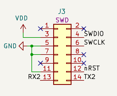
Yes, the ARM-14 header should exactly match the ST-Link V3 Mini’s cable, and also carries Serial RX/TX and nRST lines. It’s a really convenient way to work.
@VIPQualityPost 's board has the luxury of USB, but really with the ARM header you don’t need USB, separate serial port or reset/boot buttons. Just that one header will do. LCSC has really cheap ones.

image

2 Likes

For some reason or another, I have been unable to get the serial port exposed on the ARM-14 connector to work. I have the same pinout as you. Is there any trick to it? The port shows up in /dev/tty.usb* but when I listen to it or try and talk on it, nothing comes through but junk. I have set the monitor_speed in platformio.ini and the matching speed in the firmware.

Adding on to @runger comments: the ARM-14 connector is also a “safety” for development. Depending on what you do in firmware, you can make it impossible to re-flash the chip if you do things like set option bits for nSWBOOT0, reset button, forget to enable USB, etc. You can always get back into the chip with the stlink so you don’t need to worry about disabling an interface accidentally if your firmware goes wild.

So I got hung up on some things… my boards do not work right out of the box becuase you have to set nSWBOOT0. The annoying thing is that the easiest way to set option bytes is using STM32CubeProg but this requires hooking up to the chip with STLink and then updating the option bytes over SWD. I don’t want to have to do this mostly because I don’t want to have to populate the ARM-14 header on regular boards, so I was looking into how to do this.

There is a set of registers you can access in code FLASH_OPTR and if you unlock the flash you can just do FLASH_OPTR->nSWBOOT0 = 0; in order to clear the bit, but this requires having running code, which you can’t do if you are stuck in the bootloader (as I am).
It turns out the flash option bytes region is accessible as a separate memory region in DFU mode.

(base) me@mycomputer ~ % dfu-util -l
dfu-util 0.11-dev

Copyright 2005-2009 Weston Schmidt, Harald Welte and OpenMoko Inc.
Copyright 2010-2021 Tormod Volden and Stefan Schmidt
This program is Free Software and has ABSOLUTELY NO WARRANTY
Please report bugs to http://sourceforge.net/p/dfu-util/tickets/

Found DFU: [0483:df11] ver=0200, devnum=2, cfg=1, intf=0, path="1-1", alt=0, name="@Internal Flash   /0x08000000/64*02Kg", serial="208134775650"
Found DFU: [0483:df11] ver=0200, devnum=2, cfg=1, intf=0, path="1-1", alt=1, name="@Option Bytes   /0x1FFF7800/01*40Be", serial="208134775650"
Found DFU: [0483:df11] ver=0200, devnum=2, cfg=1, intf=0, path="1-1", alt=2, name="@OTP Memory   /0x1FFF7000/01*01Ke", serial="208134775650"

so the flash option bytes region is “alt-1”.
you can read this region to a new file on your computer like this:
dfu-util -a 1 -s 0x1FFF7800:48 -U optionbytes.bin

so I read a “configured” device, and now have the option bytes stored as a file, I can just write these in DFU mode to new/unconfigured devices:
dfu-util -a 1 -s 0x1FFF7800 -D optionbytes.bin

Unfortunately it seems this area is locked. Few people seem to have attempted option bit programming over DFU so there are not a lot of resources. The reference for the chip mentions that there is a sequence you need to follow when programming this area, but I was hoping it would be unlocked over DFU. There might be some workarounds but this doesn’t seem to be a good way forward, at least for now.

OK, actually it works!
The reference for G431 says that the option byte memory is 48kbyte but actually it is just 40kbyte.
Instead of forcing a 48kbyte read (-s 0x1fff7800:48) I just let it read to the end of the memory region:
dfu-util -a 1 -s 0x1fff7800 -U optionbytes.bin
the region only seems 40kbyte long.
This new file works fine when I write it back, so you can set the option bytes once on one board (to configure with GUI if you don’t feel like bit-fiddling) and then just dump/flash them over dfu later without needing to futz with the ST tools (too bloated for my taste). I then set a factory option bytes config with CubeProg and re-flashed over DFU and everything seems in order- it does actually write all the options.

2 Likes

Nice detective work!

This sequence should just be a command in dfu-tool… I think it would help a lot of people!

Regarding the arm header, which UART did you connect to it? I suspect the UART level isn’t initialized right, because normally this just works real easy

Are you still having trouble with Serial? I presume you can do serial on usb or are you having a problem with both. I can post my code to a repo if you like.

I’m going deep on the CAN at the moment. I might have a go at making a commander equivalent for canbus. i.e. you can control pretty much everything over can without reinventing the wheel. It’ll be fdcan initially but I’ve got an f4 and esp32 with can somewhere to.

Serial over USB works fine, so that’s what I’ve been using- it’s just the STlink VCP that doesn’t seem to want to work.

I’m also knee deep in CAN! Let me know if you get something working… I am trying a few different things for a similar purpose to create a more flexible interface. But it’s slow working for me because I am learning a lot from scratch, I never used this peripheral before :slight_smile:

1 Like

I’ve got CAN working but its not particularly tidy - will pull it into a library in the next week or two.
I was thinking of splitting the 11bit identifier into:

  • first 4bits = device_id. This will give up to 16 devices. I’ll probably reserve first device as broadcast i.e. all devices will listen to this as well as their normal device id
  • next 4 bits = domain. 16 domains (per device). An abstract concept - e.g. could be velocity_pid
  • last 3 bits = metric. 8 metrics (per domain). Again abstract e.g. could be P term (of PID)

So when a device starts, it’ll do a MASK filter for its own device (and broadcast device) so that it’ll only receive messages targeting it.

I can subscribe to data frames and remote frames and send dataframes. I’m trying to come up with a sensible mapping for the CAN ID Schema which will likely be heavily influenced by SimpleFOC commander gcode-like approach.

Please take a look at the SimpleFOCRegisters code in the drivers library. It’s a work in progress, but the ultimate goal is to have set of standard registers which map to SimpleFOC s configuration and telemetry. These will be used across I2C, Serial (binary) and CAN communication, as well as the settings storage abstraction and telemetry.

been a while since I’ve been in the thread… but I have CAN working!
there is surprisingly little documentation about using FDCAN with STM32duino. Here are my notes:

  • check that each end of the bus is terminated (120R each side, total bus impedance 60R)
  • Check that your FDCAN peripheral clock is reasonable- see link below. Lower clock speed gave me better results for generating the timing clock segments- there are some restrictions about how large they can be.
  • setup CAN in cubeMX, then generate code:
    • copy over the functions MX_FDCAN_Init, HAL_FDCAN_MspInit, HAL_FDCAN_MspDeInit to your own code. The init function has some properties that are specific to the peripheral clock and transceiver and need adjustment
    • Also copy the SystemClock_Config function from the main.c in src.
    • you have to write your own TxHeader and filter struct, there are many guides online about this. You also make a small buffer to put the data that you want to send in.
    • you have to declare your own FDCAN_RxHeaderTypeDef for the received data to be handled, as well as a buffer to put the data into.
    • you have to implement FDAN1_IT0_IRQHandler, HAL_FDCAN_IT_RxFifo0Callback if you want to have interrupts. The IRQHandler needs to have extern "C" in the front in order to get linked with the irq vector table properly, otherwise the interrupt will be unhandled and the program will hang.

To get all of the parameters for the FDCAN handle before you init the peripheral, you can use this online tool, you need to check the datasheet for your crystal and the transceiver, and the peripheral clock (I ended up using HSE 12MHz) : https://www.kvaser.com/support/calculators/can-fd-bit-timing-calculator/

The correct order to get everything working is like this:

  • Make sure that HAL_FDCAN_MspInit is set up to use the right GPIO pins for where your transceiver is connected. If you are using interrupts make sure that NVIC priority and IRQ enable are setup in this function too.
  • Make sure that your SystemClock_Config() is set up with the proper clock speed, including the peripheral clock speed for the FDCAN instance.
  • Create and configure FDCAN_HandleTypeDef struct, using parameters from above link
  • Call HAL_FDCAN_Init
  • Configure your FDCAN_FilterTypeDef
  • Call HAL_FDCAN_ConfigFilter
  • Configure your FDCAN_TxHeaderTypeDef
  • Call HAL_FDCAN_Start

if using interrupts, you additionally have to enable the interrupts:

  • Call HAL_FDCAN_ActivateNotification
  • The received messages will trigger HAL_FDCAN_RxFifo0Callback- you can put whatever code you want in there.

If not using the interrupts, you can read the data like this:

  • Call HAL_FDCAN_GetRxFifoFillLevel to see how many messages are in the FIFO
  • Call HAL_FDCAN_GetRxMessage to pull the message from the FIFO into the Rx buffer
3 Likes

Trying to find a way to detect if the USB connection is enumerated seems kind of useful, but not a lot of things online are very helpful. I did find that this reliably can tell you not only if a USB cable is plugged in but if the device is enumerated as well:

USB->DADDR & 0x7F

will return non-zero if the device is connected to anything (enumeration address register)

1 Like

Hey, I’m looking into designing a similar board for my project and found your board :slight_smile: Since I’m kind of new to the whole STM32 system I wanted to ask what the .ioc file in the repository is for? Would I need to flash these settings to the MCU to have the right timers and gpio settings or is simply compiling in with PlatformIO enough?

1 Like

The .ioc is the file that you can open in CubeMX for graphical view of the pinout, I use it when I am determining the pinout :slight_smile:
You can just open the project in pio and build and the firmware should just work right away. I don’t recall if there is any specific application logic in the repo but all of the “configuration” stuff should be in there and you should be able to start turning a motor pretty quickly.

1 Like

Hi, I had some of your aioli-foc boards made with JLCPCB assembly service and tried to bring them up. Uploading via ST-Link in PlatformIO completes, but the code does not start. When debugging, it seems the MCU hangs in the reset handler.
Trying to access the MCU with STM CubeProgrammer crashes CubeProgrammer, despite other MCUs like SM32F411 and STM32G031 working with the setup (same STLINK-V3MINIE and same CubeProgrammer).
Using dfu as upload protocol in PlatformIO seems to work, as the motor wiggles a bit and the Serial port is visible and showing messages. However, after a reset, the program seems to be gone.
I am using a M2 MacBook Air with macOS Sonoma.
Did you have similar experiences? Or can you point me in the right direction to get these boards going?
Thanks a lot in advance.

The trick is that because I used CAN and USB, PB8 can’t be used for BOOT0. So you need to set the option bit nSWBOOT0 to unchecked, so that it will not try to read this pin on reset. The only impact about this is that you can’t enter DFU via hardware pin. However, I put some code in my repo posted above, you can jump to the bootloader to enter DFU via application, so I just use the User button as a general GPIO to enter bootloader rather than the hard-coded DFU / bootloader entry via PB8.

I’m glad to know the boards were interesting to other people! What sort of project are you making with it? Was the ordering process from JLC straightforward?

Thanks for the info. I will need to see how to set the option bit. I need CubeProgrammer for that and it always crashes when connecting to the STM32G431 MCUs. Other MCUs work. It is really sad, that ST does not really support platforms other than Windows. The software they have for Mac is really buggy, ST-Link v3 only works over a USB2 hub, and so on.
I am looking into something smartknob-like with haptic feedback. Your board looks to be a very compatct platform for that.