Hi!
New board arrived, I’ll be posting about my bringup in here…
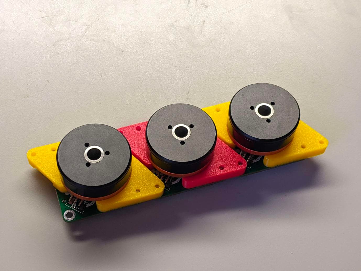
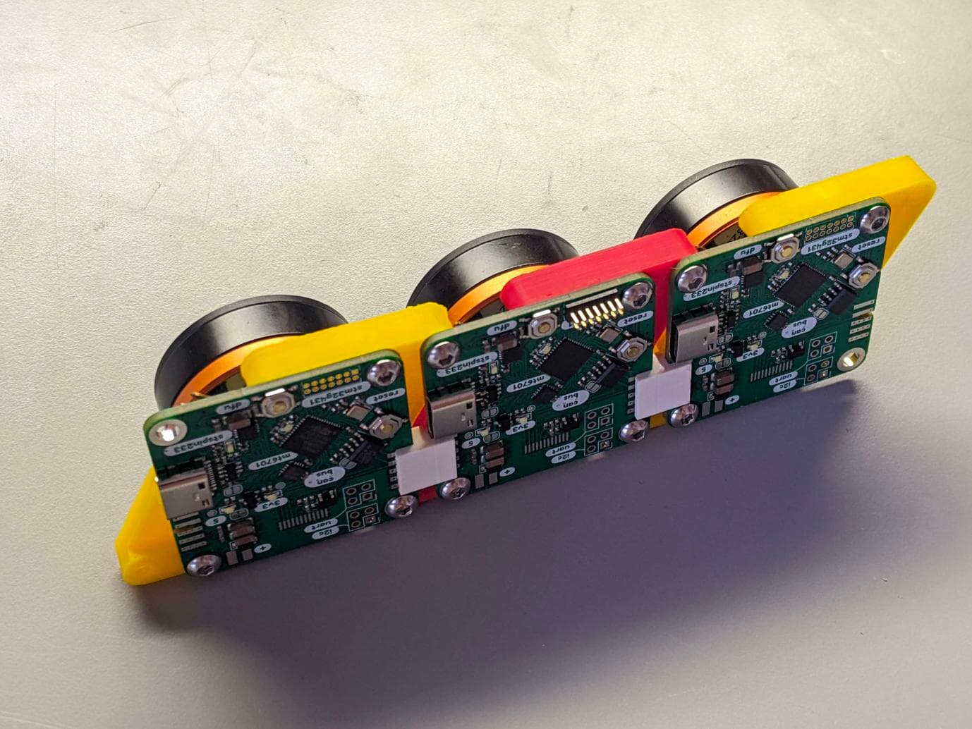
It’s another USB powered AIO- this time based on STM32G431, with the STSPIN233 driver and MT6701 magnetic encoder. Here is the Github for the project.

Thanks so much for sharing this. I’m spending a few hours looking through your kicad and firmware. There a loads of cool features (tft display, dual board2board connectors, usb/dfu), on this board and your platformio structure is much nicer than what I’m doing.
I’m developing a similar board, same mcu, CAN, but with slightly more power (DRV8316 20v 2A), different sensor (ma730). Be interested in how you get on with your sensor as it is cheaper. I’m also considering ditching my current sensing (is it that useful for slow speed gimbal motors?). Apart from power, I might converge my design towards yours.
How much of this was assembled by jlcpcb? Did you have to solder any components yourself? Is there a BOM file?
Happy to collaborate on firmware too
Thanks @Owen_Williams !!
It’s mostly assembled at JLC, other than the STLink 2x7 header, I2C/UART headers (I didn’t intend to have these populated, I rather just solder wires direct to board) and the TFT (this actually doesn’t have a connector but solders directly to PCB, mounted backwards), and the FPC motor connector on backside, e.g. what you see in this picture is how it comes. The BOM cost comes out to ~ $9.50 per board. I can shoot you over the BOM & CPL file I used- I don’t usually include those in my repo because they can be generated from KiCad but it’s true that it’s not de-facto in JLC format so maybe I should put them up.
A similar board with more power would be great! I would be happy to collaborate on something like that too.
Firmware is the weakest part of this project- I’m not a great programmer. For me now I am wrestling with some implementation details related to CANbus. I’m happy to take any help I can get!
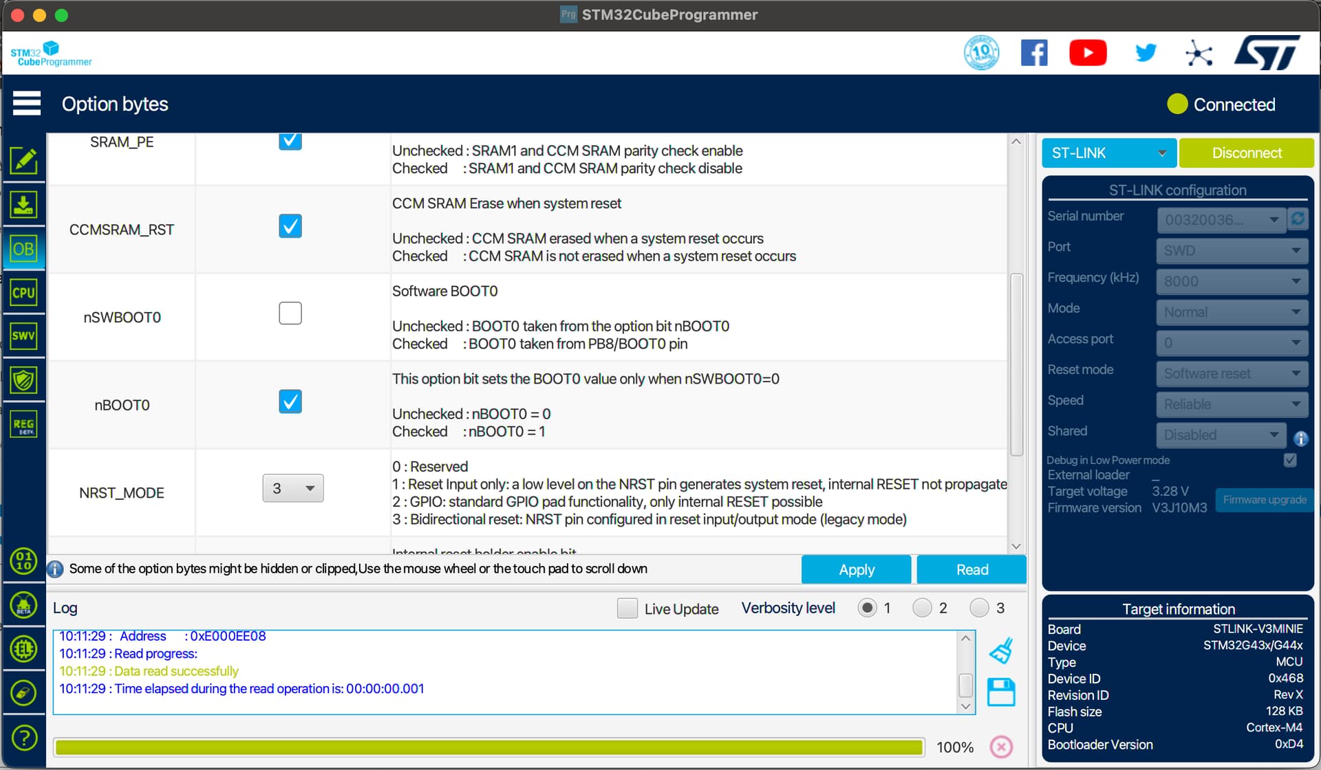
So the first thing to do is fix the nSWBOOT0. This is an option bit that sets when to enter the bootloader- if you have this enabled, there is a hardware entrance to bootloader if you pull the pin low. But this pin is shared with the FDCAN peripheral, so I don’t have any pullup here (e.g. it always boots to bootloader, instead of program memory). You can set the option bit with STM32CubeProgrammer (I’m not sure if it’s possible to do this from platformIO)
After setting this bit now I have blinky!
Bringup has gone concerningly smoothly..
Time to start working on linking CAN between boards!
Nice! Maybe this will advance us towards a main flagship board. Or be useful on it’s own, of course!
I think it’s too low-power for most people on this board, it’s just peanuts in comparison… although of course I would love for it to be popular.
But I’m happy to contribute some firmware tricks towards anyone else using G431CBU6 (namely using CAN with DFU mode since there are pin conflicts that I think I have resolved)! These are very cheap on JLC now and so I think quite a few people are working on some designs so maybe we will see another boom of user boards soon.
@VIPQualityPost - glad things are going smoothly. I’m testing CAN too on my board but it’s not going particularly well. I think its a clock/peripheral thing. The firmware does init/start/writeFrame successfully but I’m not receiving on other end. I’m testing it with a usb to can converter - which I’ve used successfully with VESC and esp32. Feels like I’m close.
Interested to know how you get on with CAN.
@VIPQualityPost - I’ve got my CAN working! ![]()
Looks like we have 3 different configurations for FDCAN pins:
# disco_b_g431b_esc1
PA11 ------> FDCAN1_RX
PB9 ------> FDCAN1_TX
# my board
PA11 ------> FDCAN1_RX
PA12 ------> FDCAN1_TX
# your board
PB8 ------> FDCAN1_RX
PB9 ------> FDCAN1_TX
Whilst all pin combinations are valid - the SimpleCan.cpp you are using is hardcoding the disco_b_g431b_esc1 pins
	// FDCAN1 GPIO Configuration
	// PA11 ------> FDCAN1_RX
	GPIO_InitTypeDef GPIO_InitStruct = { 0 };
	GPIO_InitStruct.Pin = GPIO_PIN_11;
	GPIO_InitStruct.Mode = GPIO_MODE_AF_PP;
	GPIO_InitStruct.Pull = GPIO_NOPULL;
	GPIO_InitStruct.Speed = GPIO_SPEED_FREQ_HIGH;
	GPIO_InitStruct.Alternate = GPIO_AF9_FDCAN1;
	HAL_GPIO_Init(GPIOA, &GPIO_InitStruct);

	// PB9 ------> FDCAN1_TX
	GPIO_InitStruct.Pin = GPIO_PIN_9;
	GPIO_InitStruct.Mode = GPIO_MODE_AF_PP;
	GPIO_InitStruct.Pull = GPIO_NOPULL;
	GPIO_InitStruct.Speed = GPIO_SPEED_FREQ_HIGH;
	GPIO_InitStruct.Alternate = GPIO_AF9_FDCAN1;
	HAL_GPIO_Init(GPIOB, &GPIO_InitStruct);
I was hoping not to define the above at all and that arduino would work it out from PeripheralPins.c
#ifdef HAL_FDCAN_MODULE_ENABLED
WEAK const PinMap PinMap_CAN_RD[] = {
    {PA_11, FDCAN1, STM_PIN_DATA(STM_MODE_AF_PP, GPIO_NOPULL, GPIO_AF9_FDCAN1)},
    // {PB_8, FDCAN1, STM_PIN_DATA(STM_MODE_AF_PP, GPIO_NOPULL, GPIO_AF9_FDCAN1)},
    {NC, NP, 0}};
#endif

#ifdef HAL_FDCAN_MODULE_ENABLED
WEAK const PinMap PinMap_CAN_TD[] = {
    {PA_12, FDCAN1, STM_PIN_DATA(STM_MODE_AF_PP, GPIO_NOPULL, GPIO_AF9_FDCAN1)},
    // {PB_9, FDCAN1, STM_PIN_DATA(STM_MODE_AF_PP, GPIO_NOPULL, GPIO_AF9_FDCAN1)},
    {NC, NP, 0}};
#endif
But no joy! I guess we are going to need to continue to use HAL in this area
Awesome!!
I actually have barely started on CAN because I was wrestling with an issue with the button I want to use to enter DFU mode… it took me all night to find but somehow my debouncing cap on the button is too high valued or something and it just browns-out my chip when I press it and the mcu locks up. It’s only 100nF so I have no idea why this is an issue, I usually use this value for buttons and have never had an issue but after removing it the problem went away… if anyone has input on this I would love to hear it:
With debouncing capacitor on button, causes MCU lockup:

Without debouncing cap, works fine:
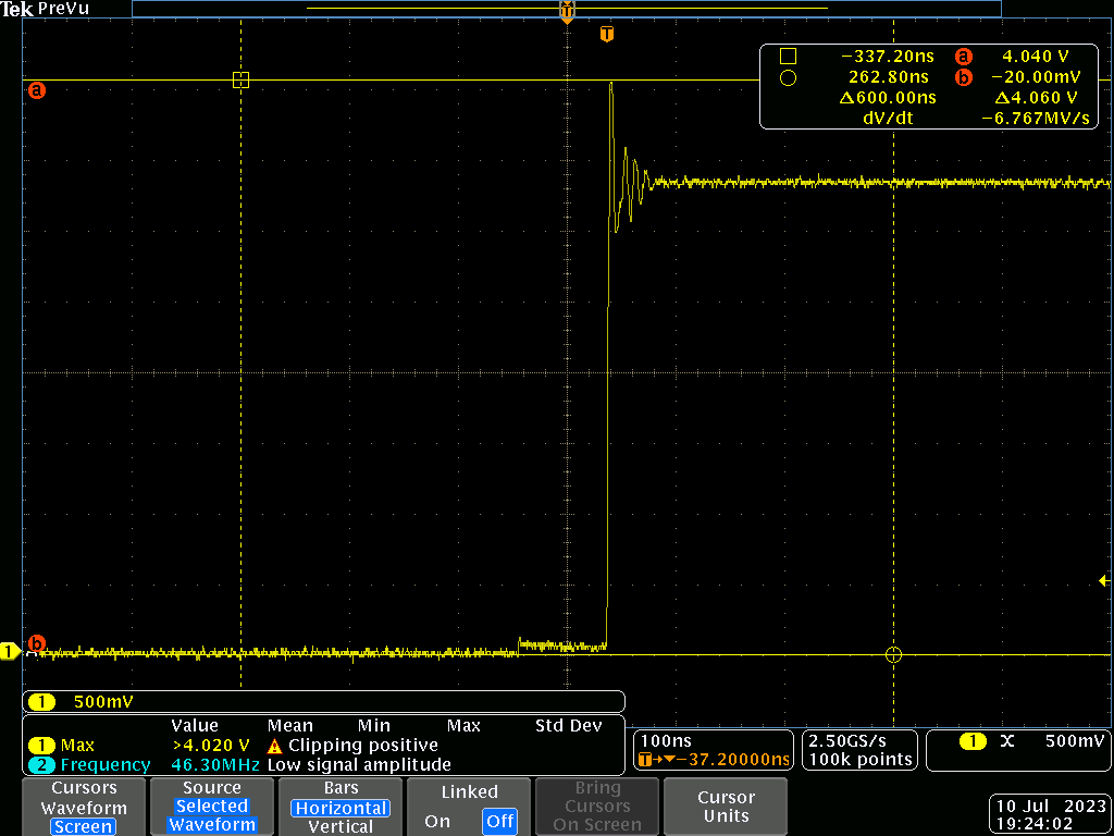
I would have imagined the ringing and higher peak voltage of (no capacitor) would be worse than the slow rise time of (with capacitor) but I’m open to hearing any explanations. I think in the future I will add some terminating resistor on the line in the future to cut down on what the pin sees…
It’s pin PC4, so it’s just a GPIO.. it should be able to handle this, and the datasheet suggests that it can even tolerate 5V. The supply rails are solid during this event too so it’s not like the rails are dropping or anything.
Finally to start moving onto the good things!!
What’s the circuit around this button? It sounds like a weird error, it doesn’t make much sense to me from your description. Are you sure it wasn’t more of a soldering problem?
Is this the pin being shared with CAN? Is it in input mode when the button is pressed?
Since I still have it in the copy/paste buffer, here is my CAN bus library which should work on your CPU: GitHub - Igitigit2/SimpleCanLib: CAN bus library for ESP32 and STM32 G431
You may have to change the pins and the part where I switch bus termination on/off, but that’s simple.
C207, page 2 of schematic: aioli-foc/hardware/stm32g431-mt6701-stspin233.pdf at main · VIPQualityPost/aioli-foc · GitHub
It’s setup pretty normal, just pulldown and a debounce cap (but I did not put an inline R- I am thinking this is the issue). This is not the pin shared with CAN- it’s just a random GPIO (PC4). I didn’t build the boards, but the soldering looked good from optical microscope and this issue shows up on all the boards so I’m sure this is it. The only thing I could think is that somehow it’s the wrong capacitance and causing some weird loading on the pin during transitions? The problem even happens if the button is configured as an output or not used at all in the code! So I think it definitely has something to do with overloading the pin, somehow.
Thanks! I’ll give this a try tonight.
You could try putting a different specimen of the same value back on there and see if the problem comes back or not? If it now works it was probably a soldering issue?
No bueno, it just does not work with a 100n capacitor installed. Someone online suggested to put a R inline with Vcc since maybe the low ESR of the cap is causing issues with inrush when the button is closed. I will revise this circuit for the next rev.
I have tried to get this to work but I think the abstraction is too high level for me to intuitively understand. I started writing a much lower level application layer for my needs. I might revisit this in the future but for now I think I will just stick with interfacing with the FDCAN HAL directly for now.
A side update: the user-button to enter DFU works! With the correct boot address, it just jumps in right away and you can re-flash the board easily. Hitting reset removes the board from DFU mode even if it’s already connected to the PC and it immediately re-enumerates as a CDC class device!

Nice. I do think it’s cool, but I really believe that a flagship board is important and would encourage you to keep an eye towards that. It seems to often arise that there is quite a large sum of issues that are hard to sort out for any given board, sensor combo, even the motor has an influence.
I fear you may run into a lot of issues getting things really working through and through, like angle mode and velocity mode, current sensing, dead time, floating point precision issues, there are so many hurdles. You can make something that more or less works in a single context, but to make a really good broadly usable tool takes a team and testing and time I think. This is one of the reasons we really need open source. Any given company stops short as soon as they have something they figure works well enough for them. Any given person stops short when they have something they figure works for them.
We are building of of each other like by using the same code base and MCU etc. which is really good though.
I’m not sure what you mean… I already have closed loop working (torque, angle, velocity modes). I didn’t implement current sensing since this is designed for gimbal-type motors which don’t really need this. Regarding dead time or floating point things, I have not had an issue with that on any project (both with integrated drivers STSPIN233, TMC6300, or with discrete gate drivers).
Your needs for ultra-quiet operation (the reason you are tinkering with deadtime, cogging?) seems to be very unique to your application and probably mostly an issue with how fast you are driving them- the motors are dead silent for me, but I am only doing relatively slow movements.
I don’t understand -this project is open source. I have a Github posted at the top with all the design/ assembly files, mechanical drawings, and firmware?
I don’t think open source means you owe anyone that you will continue working forever on the project, it just means that others can take a look or use it themselves. If you need more, then just patch up the design yourself to what you need. The application spectrum for things like this is way too wide, it’s impossible to have one board which does everything everyone wants.
Looks great and I love the colours!
I’m guessing you are having no problems with magnetism passing through pcb board to sensor. I’ve got my board ‘facing inwards’ but that isn’t quite as practical as your approach.
I’ve bought myself an stlink-v3minie, it’s tiny and I can’t plug it into anything yet - but suspect your 2x7 port is designed for it (or for the older mini).
What are you longer term plans? It is not clear what you are making?