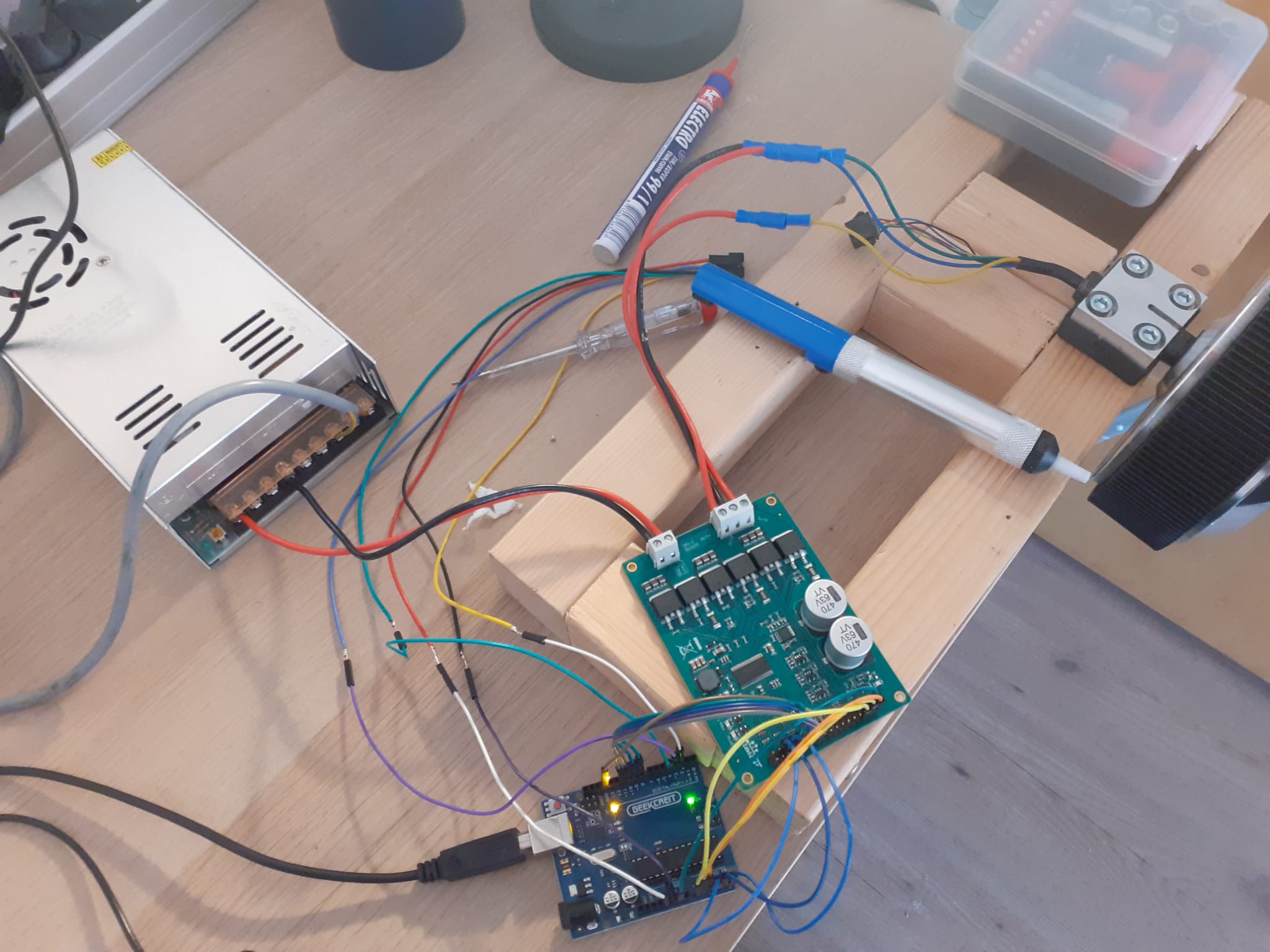
I’m struggling with the code so i hope someone can help me. For now im trying to move a hoverboard bldc motor using simpleFOC and a drv8302 but it does not want to move. from what i can see with the multimeter is that the voltage of the INHA, INHB, INHC stay around 2.4-2.5 v and that the OUTA, B and C do not receive any voltage at any velocity input. I put the code and a picture of the set up below if anyone wants to look at it.
// Open loop motor control example
#include <SimpleFOC.h>

//InH PWM pins
#define INHA   9
#define INHB   10
#define INHC   11
//miscellaneous pins
#define En_Gate  8 //Enable gate driver and current shunt amplifiers.
#define OC_ADJ   A3 //analog input adjusting the over-current limit - if you don’t care you can put it to high
#define M_OC     A4 //Mode selection pin for over-current protection options. LOW = cycle by cycle. HIGH = overcurrent shutdown
#define M_PWM    A5 //Mode selection pin for PWM input configuration. LOW = 6PWM. HIGH = 3PWM

// polar pairs
int pp = 15; // motor has 30 outer magnets
//phase resistance value of the motor A B and C wires.
float RPhase = 0.4;

// BLDC motor & driver instance
// BLDCMotor motor = BLDCMotor(pole pair number);
BLDCMotor motor = BLDCMotor(pp, RPhase);
// BLDCDriver3PWM driver = BLDCDriver3PWM(pwmA, pwmB, pwmC, Enable(optional));
BLDCDriver3PWM driver = BLDCDriver3PWM(INHA, INHB, INHC, En_Gate);

//target variable
float target_velocity = 0;

// instantiate the commander
Commander command = Commander(Serial);
void doTarget(char* cmd) { command.scalar(&target_velocity, cmd); }
void doLimit(char* cmd) { command.scalar(&motor.voltage_limit, cmd); }

void setup() {

  // driver config
  //DRV802 driver specific code
  //3 or 6 PWM put on high for 3 pwm driver
  pinMode(M_PWM, OUTPUT);
  digitalWrite(M_PWM, HIGH);
  //over current protection
  pinMode(M_OC, OUTPUT);
  digitalWrite(M_OC, LOW);
  pinMode(OC_ADJ, OUTPUT); //adjuster voltage limit for M_OC
  digitalWrite(OC_ADJ, HIGH); // for now put on high to give maximum over current limit but better to connect it with a pot meter.

  // power supply voltage [V]
  driver.voltage_power_supply = 32;
  // limit the maximal dc voltage the driver can set
  // as a protection measure for the low-resistance motors
  // this value is fixed on startup
  driver.voltage_limit = 32;
  driver.init();
  // link the motor and the driver
  motor.linkDriver(&driver);

  // limiting motor movements
  // limit the voltage to be set to the motor
  // start very low for high resistance motors
  // currnet = resistance*voltage, so try to be well under 1Amp
  motor.voltage_limit = 18;   // [V]

  motor.foc_modulation = FOCModulationType::SpaceVectorPWM;

  // open loop control config
  motor.controller = MotionControlType::velocity_openloop;

  motor.useMonitoring(Serial);
  //display variables
  motor.monitor_variables = _MON_TARGET | _MON_VEL ;
  // downsampling
  motor.monitor_downsample = 100; // default 10

  // init motor hardware
  motor.init();

  // add target command T
  command.add('T', doTarget, "target velocity");
  command.add('L', doLimit, "voltage limit");

  Serial.begin(115200);
  Serial.println("Motor ready!");
  Serial.println("Set target velocity [rad/s]");
  _delay(1000);
}

void loop() {
  motor.loopFOC();
  // open loop velocity movement
  // using motor.voltage_limit and motor.velocity_limit
  motor.move(target_velocity);
  motor.monitor();
  // user communication
  command.run();
}
Hey, thanks for the reply
Driver seems to be working correctly with the standalone as the INHA ,B, C all give different values rather than all three giving a voltage of 2.4-2.5 v
From what i know is that it can be 3 or 6 pwm depending if you put M_pwm HIGH or LOW
drv8302 chip datasheet gives:
Mode selection pin for PWM input configuration. If M_PWM = LOW, the device supports 6 independent
PWM inputs. When M_PWM = HIGH, the device must be connected to ONLY 3 PWM input signals on
INH_x. The complementary PWM signals for low side signaling will be internally generated from the
high side inputs.
Ok, so if you have it in 3-PWM mode, have you connected the EN signals? The low side inputs become enable inputs in 3-PWM mode, and you have to pull them high…
No in standalone you will check the output voltage, not the INH A, B, and C voltage. So disconnect the BLDC motor from the driver, upload the standalone code then check what voltage you are getting at the output. So in the example, driver voltage per phase is set as: ( driver.setPwm(3,6,5);). If the driver is working correctly you will get voltage 3 at phase A output, 6 at B, and 5 at phase C output.
My mistake,
im not exactly sure what i have to measure but i can say that im not getting the correct voltages.
from VIn - GND i get 31.6v, for all three VIn - OUTA VIn- OUTB and VIn - OUTC all give 31.6 v and
GND - OUTA, GND - OUTB and GND - OUTC i get 0 v.
Yeah, you are right. Unlike many other drivers the low side inputs don’t matter in 3-PWM mode. I guess that also means you can’t put the phases in High-Z (off) mode, but that might not be important for your needs.
So you can ignore the low side inputs.
Hmmm - how about the wiring, are you sure you’re using the right pins?
I have the same driver board on my desk, but I’m using it in 6-PWM mode… it is working for me.
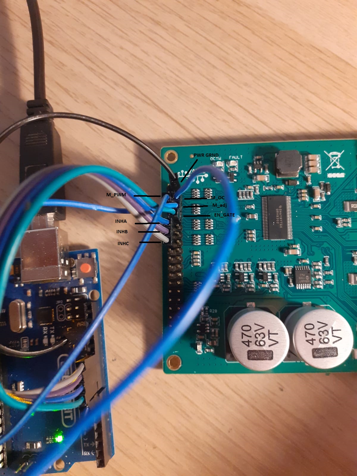
Maybe if you send a close picture of the pins, we could check the wiring is correct?
Please, can you specify how you made the connections? Like which pin of Arduino to which pin of DRV8302 board. I have used this board in 6 PWM and 3 PWM and it’s worked perfectly. Before using the open loop check the standalone example and see the driver output.
Yes, I have the same board, but I am using it in 6-PWM mode.
It is very hard to tell from the picture, but from what I can see it looks correct.
I don’t yet use the M_OC and M_OC_ADJ pins. Maybe try removing them and see if it helps? Of course you have to be careful then not to produce too much current, keep the voltage limits low!
Hey,
Been a bit since the last replay. i was hoping to figure it out by myself but i failed .
i made some better pictures i hope you guys can spot the error that i can’t.
// BLDC driver standalone example
#include <SimpleFOC.h>

//InH PWM pins
#define INHA   9
#define INHB   10
#define INHC   11
//miscellaneous pins
#define En_Gate  8 //Enable gate driver and current shunt amplifiers.
#define OC_ADJ   A3 //analog input adjusting the over-current limit - if you don’t care you can put it to high
#define M_OC     12 //Mode selection pin for over-current protection options. LOW = cycle by cycle. HIGH = overcurrent shutdown
#define M_PWM    7 //Mode selection pin for PWM input configuration. LOW = 6PWM. HIGH = 3PWM

// BLDCDriver3PWM driver = BLDCDriver3PWM(pwmA, pwmB, pwmC, Enable(optional));
BLDCDriver3PWM driver = BLDCDriver3PWM(INHA, INHB, INHC, En_Gate);

void setup() {

  Serial.begin(115200);
  // driver config
  //DRV802 driver specific code
  //3 or 6 PWM put on high for 3 pwm driver
  pinMode(M_PWM, OUTPUT);
  digitalWrite(M_PWM, HIGH);
  //over current protection

  pinMode(M_OC, OUTPUT);
  digitalWrite(M_OC, LOW);
  pinMode(OC_ADJ, OUTPUT); //adjuster voltage limit for M_OC
  digitalWrite(OC_ADJ, HIGH); // for now put on high to give maximum over current limit but better to connect it with a pot meter.


  // pwm frequency to be used [Hz]
  // for atmega328 fixed to 32kHz
  // esp32/stm32/teensy configurable
  driver.pwm_frequency = 32000;
  // power supply voltage [V]
  driver.voltage_power_supply = 31.6;
  // Max DC voltage allowed - default voltage_power_supply
  driver.voltage_limit = 31.6;

  // driver init
  driver.init();
Serial.print("Driver init ");
// init driver
if (driver.init())  Serial.println("success!");
else{
  Serial.println("failed!");
  return;
}

  // enable driver
  driver.enable();

  _delay(1000);
}

void loop() {
    // setting pwm
    // phase A: 3V
    // phase B: 6V
    // phase C: 5V
    driver.setPwm(3,6,5);
}
From what i can see it that the voltage values are phase A = 23.4v, phase B= 20.5 v, Phase C = 0 v
The values should be phase A = 3v, Phase B = 6v and phase C = 5v.
Im starting to think i might have broken the DVR8302 board and need to buy a new one.
Next problem that i have is that the motor seems to make a turn back when it is turning. sort of vibration i geuss. Do you guys know what that problem is called and what the underlaying problem might be?
I’m using “MotionControlType::velocity_openloop;”. The script is the openloopvelocity example. it might be polar pairs. currently ive put the polar pairs on 15, because i counted 30 magnets.
the motor has internal hall sensors. A suggestion i got was that the sensor have a too low resolution for the motor to work smootly. I dont think the openloop uses the hall sensors though.
is it possible to use the utility example code “find_polar_pairs_number” using a hall sensor? The only options i see for a magnetic sensor or an encoder.
Edit: found the problem .
I needed to adjust the motor voltage limiter and not give a phase resistance value. ive put it at 3 volt now and that seems to smooth things out. its seems that if i go higher the PSU and the bldc motor starts to make a noise which i think migh be a coil whine. For the phase resistance value. i measured 0.4 ohm between the AB, BC and AC values which seems correct but using this causes the vibrations.
The explenation of the voltage limiter uses the formula current = resistance * voltage. I’m pretty sure the voltage is in my case 4 as i put the limiter at 4 volt but what is the resistance and current? is the resistance the phase resistance trough the A B C wires?
another question that i have is what limiter is safer to use Voltage or Current?
you could modify the example and try, but maybe hall sensors are not precise enough for this approach…
The resistance is given by the motor windings, and you can use the value you measure (phase to phase resistance). But if you set it and the KV value then you will be controlling the (estimated) current, see our docs here: BLDCMotor | Arduino-FOC
If its working better for you without providing the resistance, you can leave it out, its not required.
Both
Always set a driver.voltage_limit to suit your application. And then for the control loop, if you have good current sensing and a fast MCU, and you can tune it well, then controlling the current is probably “safer” on a low ohm motor. But if the current control loop isn’t working well, then probably a voltage control loop is better.