Yeah, i inverted motor wires. But it still make some small angle while i run find_pole_pairs code. So i basically can write 6.28 in code and motor should turn for 360 degrees. Instead of that it goes a little bit forward and then back to start position. If i put 12.6, motor just do it two times.
I use Arduino uno with mega328p chip
Its 1.4.1 version installed with library manager in Arduino ide
I use 8,9,10 pins for A,B,C pwm and 8 for enable. I checked it many times.
You can run open loop code. The motor spins forwards and backwards (depending on +-=0.001)
you can manually spin the motor a whole turn and it correctly says 6.3 rads when you ask what the angle is
when you run find_pole_pairs it barely moves and/or moves erratically left to right
This is odd as pole_pairs is more or less the same as open loop.
Can you check that your BLDCMotor motor = BLDCMotor(9, 5, 6, 0, 8); is the same between pole_pairs and open loop. @Antun_Skuric asked about which pins you use. I guess you are using 9,5,6,8 for motor and 10 for chip select for SPI. SPI will also be using 3 other pins (11, 12 and 13 is common for Uno I think). Uno is also using 0 and 1 for serial port. Does that sound right?
I’d get a fresh copy of pole_pairs especially if you’ve made changes e.g. to pp_search_angle
I solved this problem. This happened only because im completely bad at coding and even didnt analyze it.
So imagine my situation:
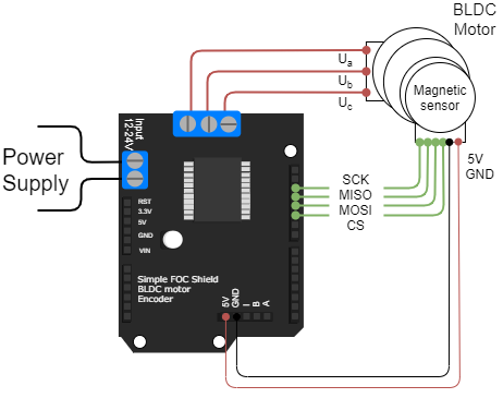
Im a complete noob at coding and i tried to use step by step information from @Antun_Skuric video and from documentation. So when i was soldering this pcb, i didnt know which pins i should solder. So i just opened the video and there were following pins:
So i just connected everything as it is shown in the picture.
Then I tried to use the code examples. So I had next motor configuration: BLDCMotor motor = BLDCMotor(9, 10, 11, 14(number of poles), 8);
And at that time I didnt even realise that I had to change my pins in:
MagneticSensorSPI sensor = MagneticSensorSPI(10, 14, 0x3FFF);
It is due to the fact that I connected the sensor by tutorial and i thought that everything would be alright.
And after all these steps I got my problem. And the problem was: the motor uses 9,10 and 11 pins, and at the same time the magnetic sensor uses 10,11,12 and 13 pins.
I just changed the soldered pins on my pcb and changed them in the code. And it is working now!
Glad to hear you got there! Now you can have some fun getting the PI tuning sorted. That’ll be a few more hours head scratching!
I find a combination of calling motor.monitor() in the main loop() and viewing the output in a serial plotter invaluable. You’ll be able to see how the velocity wobbles and settles as you change your PI and Tf tunings. Don’t try angle control mode until velocity control mode is stable. Angle control mode requires you to have a nicely tuned velocity PI and Tf values.