Also the driver is out of stock, how do you do this?
For prototypes I am going to buy the driver tmc6100/tmc6200 from mouser or digikey where they are in stock and put it on myself. Still about 5k tmc6200 and 2k tmc6100 available. If I ever were to make many of these I could always use a different vendor and send in a tape reel. I’m going to order a stencil that will fit over the driver chip spot and then reflow the board.
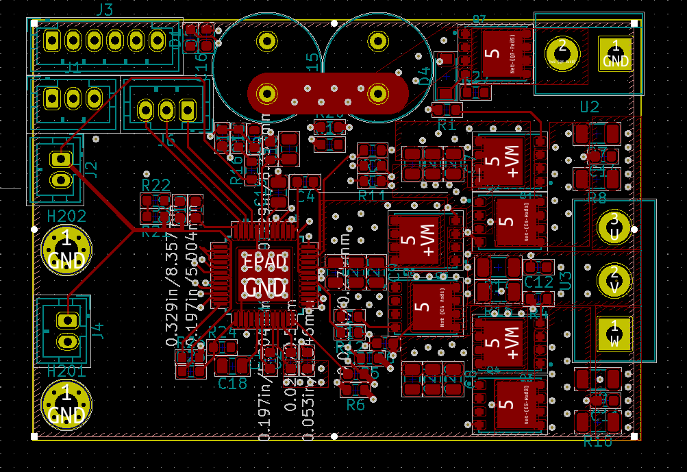
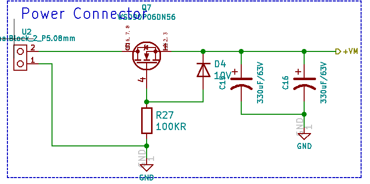
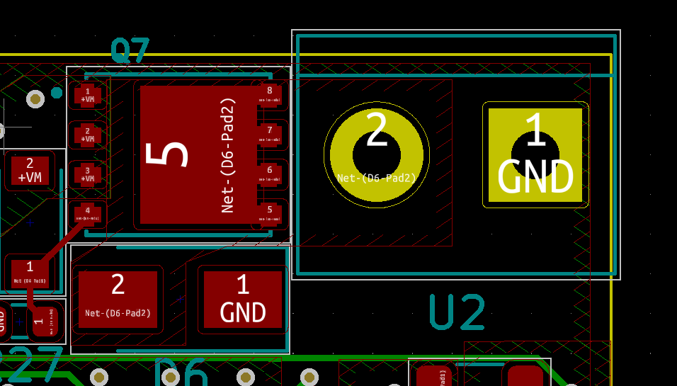
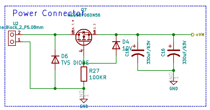
polarity protection and fan controller
I made an attempt at the revere polarity protection. I could not find a better P channel mosfet than the WSD90P06DN56 you suggested so I used that one.
I did not add the esd/voltage protection yet. Not sure about the TVS diodes. A 48V lipo battery system can reach 58V when fully charged so I would need a reverse standoff voltage of 58V. Breakdown voltage would start at 64V and clamping at 93V. So not sure if the circuit is already damaged at this point. I think I could get an 8 amp TVS diode to fit since those are around 4mm by 6mm.
You will reflow the QFN package on a pre-soldered board, that’s interesting. Let me know how it goes, I’m very curious. It’s not an easy task.
At higher voltages the LiPo packs have very large swings between fully charged and partially discharged states. I always assume users must have a pre-regulated voltage supply rather than attaching directly a battery pack, unless you aim for the middle of the range of the intended battery pack. Also, the ESD protection is not just for simple overvoltage from, let’s say, 60v to 90v, but main purpose is to protect against high voltage from accidental static discharge which will silently kill your sensitive signal / logic silicon. In the winter, when air gets dry and you easily build up static electricity, it’s trivial to discharge 10kV at fairly high current into you board. This is a hobby board and people will touch it with bare hands all the time.
Ultimately these are your decisions, I’m only providing my unsolicited input.
About ready to make an order from LCSC. They have all the parts except the gate driver TMC6200 which I will order from mouser/digikey.
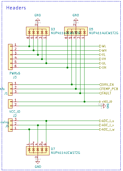
Not sure if I should add pull up resistors to the 3 ADC current lines. I have seen that done on the example board. I could always put 0 Ohm resistors on those lines?
You have to choose the shunt resistors and set the gain appropriately (x5, x10 or x20), and you can use the VOFS pin to choose the centre-point for the output. If you picked it all right, you should have an output within the range of the MCU you intend to use.
You could consider adding a filter, and you already have ESD protection so I would leave it at that for a first version and test it out… if you find the output too noisy you can always come back to the idea of a filter then.