Hi @NINAD_RAGIT . For the control of two gimbal motors you will need 4 TB6612s because we need 3 half H-bridge per motor. This is a trick because those drivers are done for DC motors driving and not for the control of BLDC motors. This way one of the two driving board is fully used while the second one is only half used.
Hi Group,
I am a complete noob and new member and found my way here while trying to figure out how to drive a small gimbal motor. I got the L298N and I’ve wired everything up just like Antun_Skuric’s example above and loaded that code as well.
But the motor won’t spin. I hope I might resurrect this discussion from a while ago to find some help. Can anybody here take a minute to look at this?
I hope I can get some clues to how to get this running. Here is the motor I’m hooking up…
I copied @Antun_Skuric 's code above, activating OUTPUT for pin 8 (see below). I think I wired everything correctly, but with power nothing happens. For my project I just need to figure out how to get the gimbal to spin with continuous rotation at various speeds. There must be more that I need to configure here. I don’t understand all the brushless motor specifications, but this one has 14 poles, KV 80 and with 6-14v operating voltage.
Any tips would be greatly appreciated!
// Open loop motor control example for L298N board
#include <SimpleFOC.h>

#define IN1 11
#define IN2 10
#define IN3 9
#define IN4 8

// BLDC motor & driver instance
// BLDCMotor motor = BLDCMotor(pole pair number);
BLDCMotor motor = BLDCMotor(7);
// BLDCDriver3PWM driver = BLDCDriver3PWM(pwmA, pwmB, pwmC, Enable(optional));
BLDCDriver3PWM driver = BLDCDriver3PWM(IN1, IN2, IN3);

void setup() {
  // deactivate the OUT4 output
pinMode(8,OUTPUT);
digitalWrite(8,LOW);


  // driver config
  // power supply voltage [V]
  driver.voltage_power_supply = 5;
  driver.init();
  // link the motor and the driver
  motor.linkDriver(&driver);

  // limiting motor movements
  motor.voltage_limit = 3;   // [V]
  motor.velocity_limit = 20; // [rad/s]

  // open loop control config
  motor.controller = MotionControlType::velocity_openloop;

  // init motor hardware
  motor.init();

  Serial.begin(115200);
  Serial.println("Motor ready!");
  _delay(1000);
}

float target_velocity = 2; // [rad/s]

void loop() {
  // open loop velocity movement
  // using motor.voltage_limit and motor.velocity_limit
  motor.move(target_velocity);

}
1 Like
You can definitely get this working. Check operation of everything with an oscilloscope stage by stage. If there is current through the motor you should be able to tell when you try to turn it as it will resist. I noticed your power supply is 5 volts in the code. You could try a higher voltage, that might help.
I wouldn’t connect the motor until you can verify everything with a scope, you may burn out the motor, as I said the rated voltage means nothing in this context.
I always used motor.target(rads/s), then just call motor.move() at high frequency, I don’t know if the proper way to do it is to call motor.move(rads/sec).
Hey @Richard_Torsney, welcome to SimpleFOC!
It’s not clear what is wrong from your code… would you mind sharing a picture of your setup so we can see the pin connections?
One thing that might be a problem is that the 5V is very near the lower limit of the board’s input? Have you tried increasing the voltage a little, to 6V or 8V perhaps?
@Richard_Torsney you might need to check output pins as in my case it was out1 out2 and out3 instead of out4
btw which one is the middle phase among these how do you figure it out
I am not sure I understand the question?
What do you mean by “middle phase”?
For the motor, it does not matter which phase output is connected to which motor phase. You can switch them as you wish. Switching any two will change the direction the motor turns.
2 Likes
I’m pretty sure I have the connections right per Antun’s diagram above…
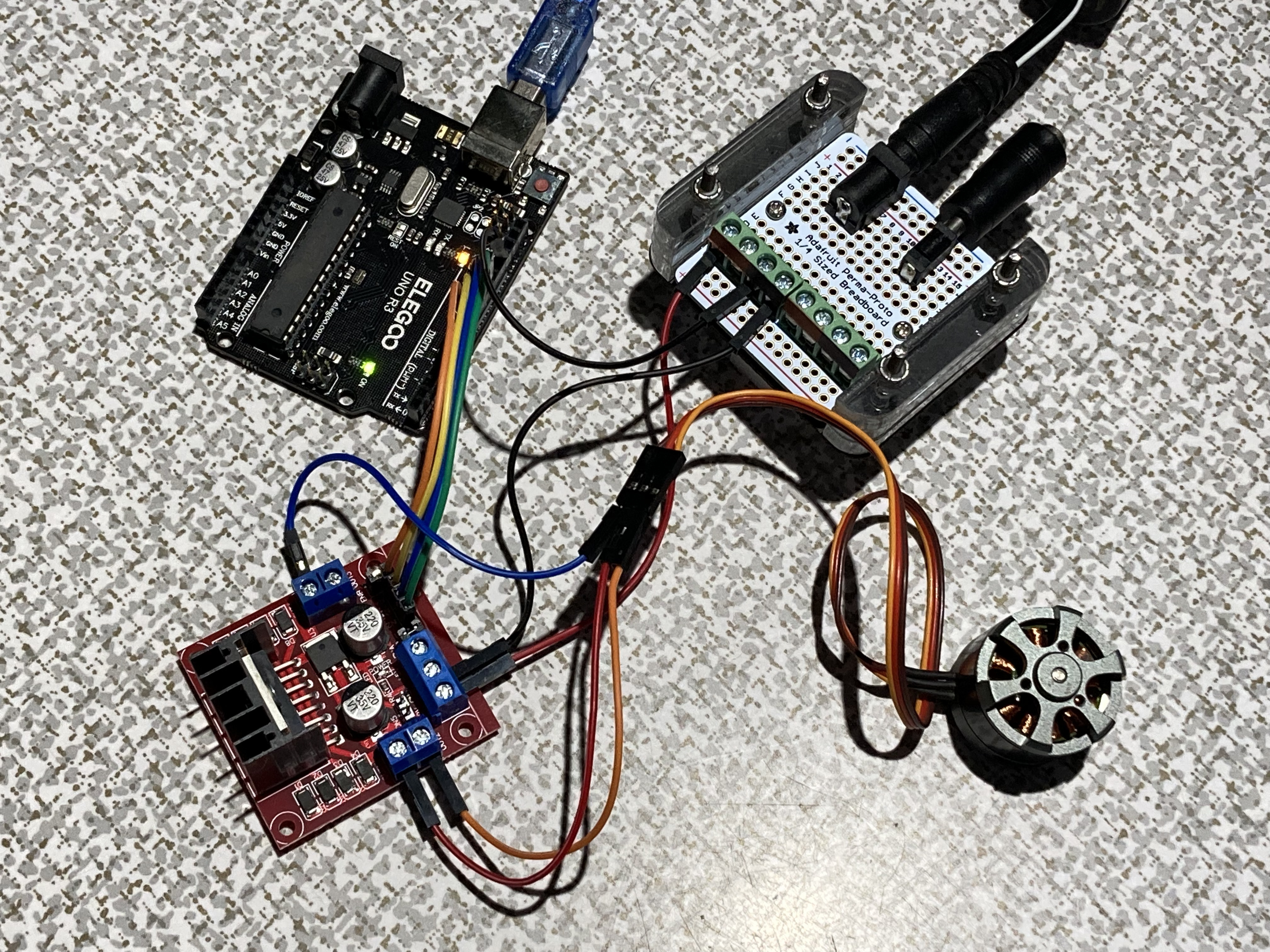
I switched power supplies and changed board power input to 12V with no apparent change. Also experimented a little with motor.voltage_limit = ; (hope I didn’t burn it out) also with no result.
One small thing you might have missed from my code above is a change to one line. The compiler gave me a “has not been declared” error for this line…
motor.controller = ControlType::velocity_openloop;
…so I made this modification that I found with a search somewhere else (can’t remember where)…
motor.controller = MotionControlType::velocity_openloop;
Here’s the whole thing with changes…
// Open loop motor control example for L298N board
#include <SimpleFOC.h>

#define IN1 11
#define IN2 10
#define IN3 9
#define IN4 8

// BLDC motor & driver instance
// BLDCMotor motor = BLDCMotor(pole pair number);
BLDCMotor motor = BLDCMotor(11);
// BLDCDriver3PWM driver = BLDCDriver3PWM(pwmA, pwmB, pwmC, Enable(optional));
BLDCDriver3PWM driver = BLDCDriver3PWM(IN1, IN2, IN3);

void setup() {
  // deactivate the OUT4 output
pinMode(8,OUTPUT);
digitalWrite(8,LOW);


  // driver config
  // power supply voltage [V]
  driver.voltage_power_supply = 12;
  driver.init();
  // link the motor and the driver
  motor.linkDriver(&driver);

  // limiting motor movements
  motor.voltage_limit = 6;   // [V]
  motor.velocity_limit = 20; // [rad/s]

  // open loop control config
 // motor.controller = ControlType::velocity_openloop;
 motor.controller = MotionControlType::velocity_openloop;

  // init motor hardware
  motor.init();

  Serial.begin(115200);
  Serial.println("Motor ready!");
  _delay(1000);
}

float target_velocity = 2; // [rad/s]

void loop() {
  // open loop velocity movement
  // using motor.voltage_limit and motor.velocity_limit
  motor.move(target_velocity);

}
Looking at the setup, I am not sure what is up.
The L298N board I have has +12V on the outside end of the power terminal. The middle is GND, so if you apply somewhere in the range 7-12V to this power input, like in your picture, then you should get a red light like this:

If the LED doesn’t come on when you apply power it’s probably time to get a new one… luckily they’re super-cheap!
2 Likes
THanks. I will check power connections again. I had not looked closely, but wondered if there was an indicator LED. I have not seen it light up at all.
Well I double-checked the connections, tried another 12V power supply and also hooked up the second L298N that came in the 2-pack and still can’t get that LED to light up. It looks like I received two duds.
Oh man, sorry to hear that!
These drivers are very cheap, so maybe the quality control isn’t that good. I bought mine in a 10-pack ![]()
Anyway, if they work I did not find them hard to use, so the fact you’re having so much trouble along with the LED not coming on does very much indicate they may just be broken.
If you get working ones they should be quite easy to set up, but fair warning: don’t expect great performance from this driver even if it works as expected…
2 Likes
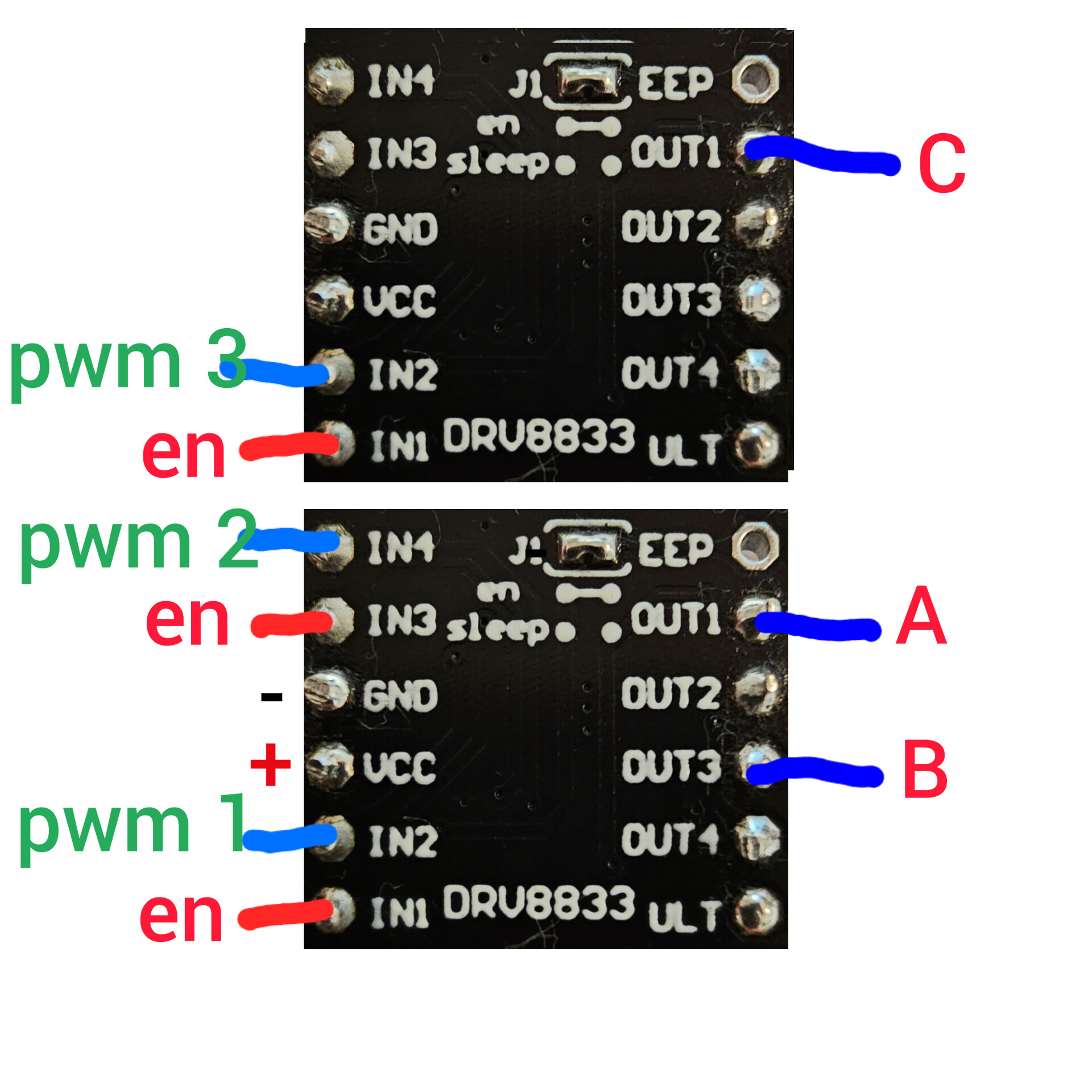
Hello. I don’t know how correct this is. But I was able to start the engine in 3 pwm mode according to the following scheme
2 Likes
This thread is pretty quite for some time.
I wanted to asked experts here if 3 phase gate driver linked below is suitable for SimpleFOC ?
The datasheet is in Chinese so everything is not clear to me but hoping that some sharp mind can figure it out. From application diagram it looks so simple and it can provide provide 5V to micro controller from built in LDO.
Thanks.
Little more details for BDR6300 about brushless motor application design on their website linked below:
http://www.bdasic.com/newsinfo/4637892.html
Thanks.
From the driver docs it would seem that it could be used by simplefoc in 6pwm mode. It also has a 60ma 5v ldo, probably too small for an mcu but ok for sensor. There is a table that describes some of the characteristics of the mosfets it should be paired with.
The docs aren’t great and the driver is basic, with no options to configure anything. I imagine there is no protection (shoot through, over voltage, under voltage, etc). So the software and your decisions will need to ensure the mosfets don’t get fried.
Simplefoc can do software dead time insertion, but it is very hardware specific and requires you to know a fair bit about your mcu and simplefoc.
It isn’t clear wherever inputs support 5v or 3.3 or both.
1 Like
@Owen_Williams Thank you for your reply.
For micro controller I will use BLE capable micro CH582F GitHub - WeActStudio/WeActStudio.WCH-BLE-Core: CH573F/CH582F/CH592F Core Board with BLE 4.2&BLE 5.3 which will use less than 60 mA. It support either 5V or 3.3V supply as it has built in LDO.
I am not too worried about protections as it will be used for specific use case only i.e. curtain control.
Isn’t it more flexible in terms of configuring everything in software?
I am confused about mosfet selection. I need atleast 24V for mosfet supply with 3A current. Do you know any mosfet package which contain 3 n-channels and 3 p-channels suitable for this chip?
Thanks.
@Owen_Williams Does this look suitable mosfet package?
Thanks.
Hey @happytm ,
This would probably work, but this is quite an old technology. More modern MOSFETs will switch more quickly, and have lower resistance (Rdson), which is better for motor control.
Still, if you’re trying to make a small board size an integrated chip like this can make sense. But I would really advise you to look at a more modern solution. If you are happy with the 3A/10A limit of this chip (and realistically it will be lower) then maybe you should look at the DRV8313 or DRV8316 from Texas Instruments… these are integrated driver + FETs in one small chip, with easy control directly from the MCU. They use only N-Channel FETs, and integrate the charge pumps needed to switch the high sides.
If you do want to make your own bridges with discrete FETs, then you should prefer solutions using only N-Channel FETs, the P-Channel ones are always less efficient. N-Channel only half-bridges need special circuits for switching the top side FETs, but most FET-drivers work in this way, so its not really a problem.
When choosing FETs you obviously have to choose ones suitable for the voltage you want to use, but then you should look at the Rdson, and the switching times, as well as the thermal properties of the package.
One rough way to compare FETs is to use the “FOM” (figure of merit) approximation: multiply the RDson by the total gate charge. The lower the better.
So I’d recommend something more like this:
![]() what a nice FET!
what a nice FET!
Obviously this will do a lot more than 3A ![]() but if you only need low power levels then I really strongly recommend the integrated solution, it will be much easier for you…
but if you only need low power levels then I really strongly recommend the integrated solution, it will be much easier for you…
SimpleFOC doesn’t support these MCUs at the moment, so you’d have to write your own low-level PWM drivers and stuff… I would not recommend this for a first-time board, it’s an unneeded complication and will take a lot of time.
I’d pick a nice easy to use ESP32, or STM32 MCU, which we already support…