Somehow all the opensource BMS circuits are using resistors to burn energy for balancing (passive balancing). Active Balancing transports energy from the strongest battery to the weakest, thereby increasing the overall range, since the weakest battery determines when the entire pack is done.
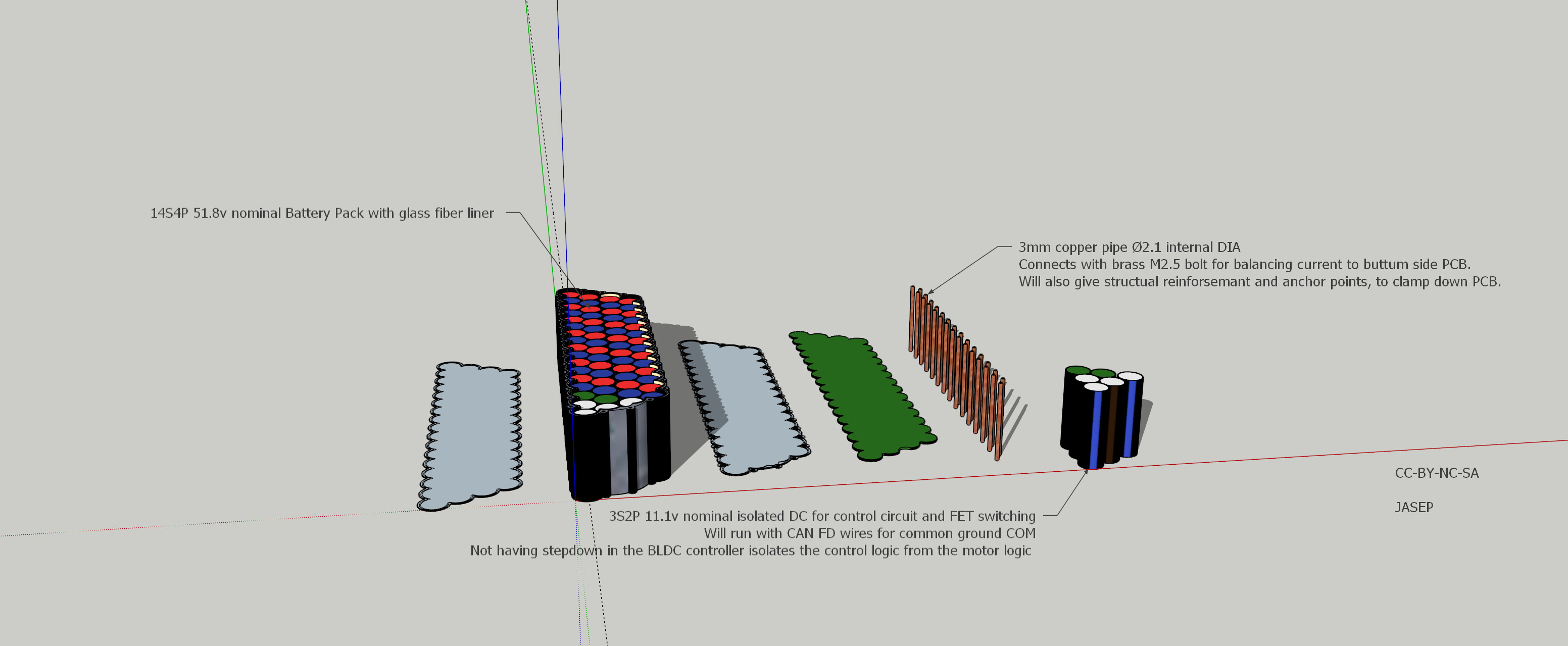
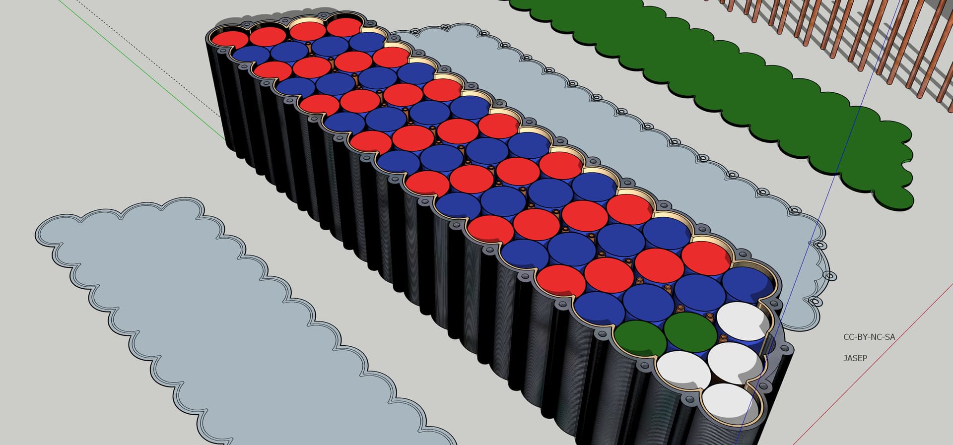
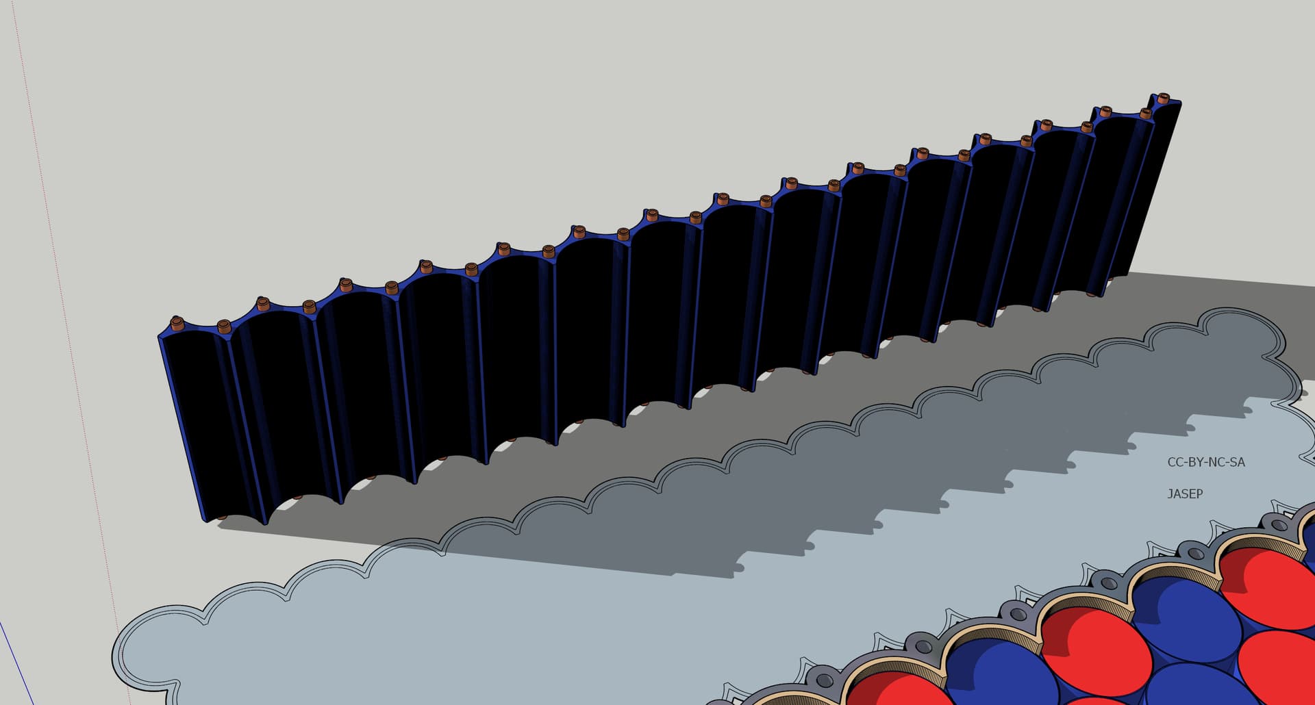
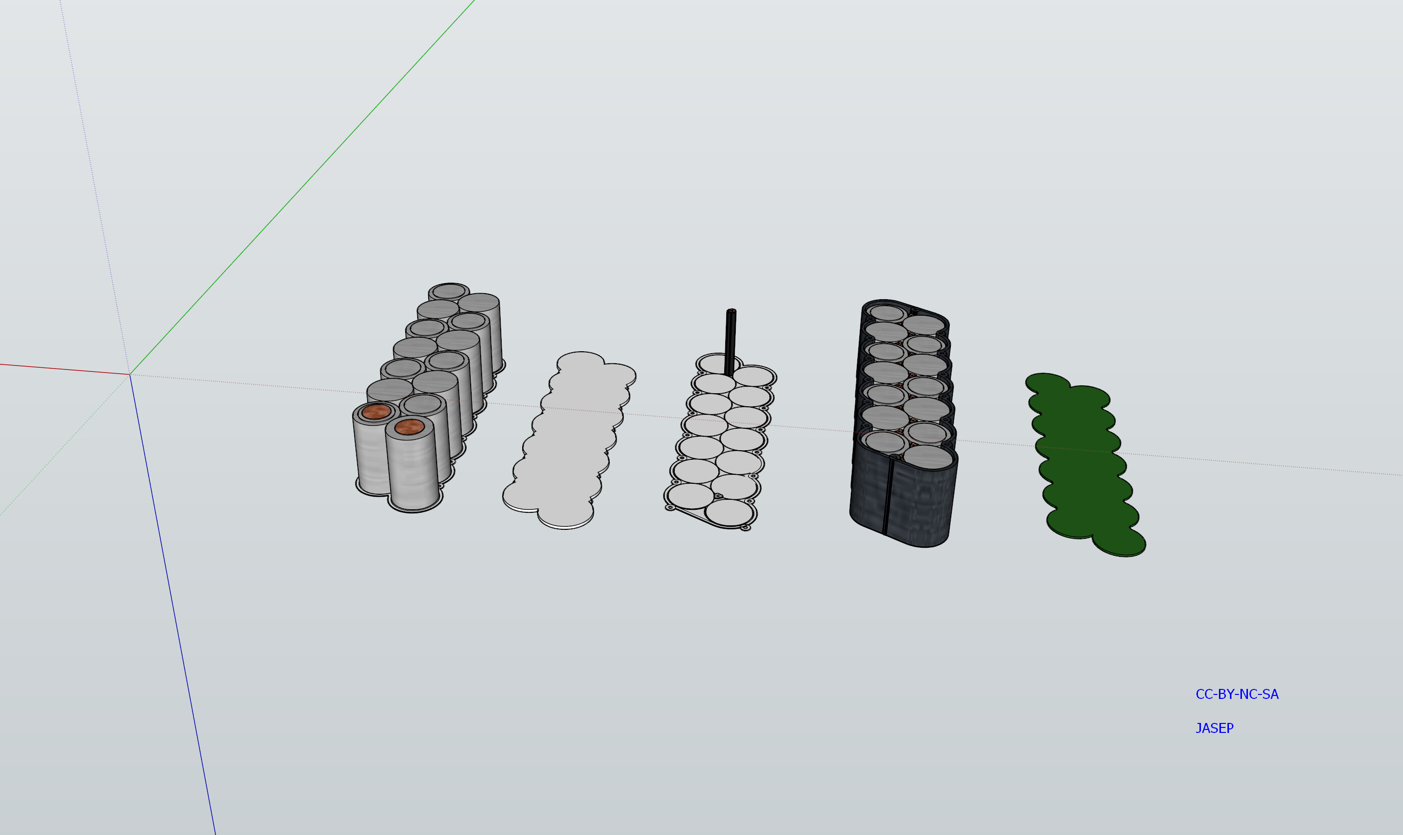
The idea is to do a integrated PCB design, which uses 3mm diameter copper pipes, to connect the top side with the bottom side PCB. With the large width of the trances between cell´s, the copper can be kept relatively thin, lowering cost and resistance.
If you know about a opensource Active Balancing project, plz let us know. All ideas are welcome !
Edit: 28-04-2022 The circuit design has taken several turns since the initial idea. Active Balancing is given up, since it simply is not worth doing for a “small” 14S4P battery. A passive balancing approach with top balancing is more then fine. There are many factors involves when it comes to how often the BMS will balance the sell´s, especially if the cells are of different age and use could there arise some imbalance.
The 4680 battery is in the event horizon, so why not use that. I think 2170 are better for a eMTB frame battery. The constellation of smaller cell´s makes it possible to utilize the full width of the PCB for cell to cell current flow. Yes 4680 do look promising, especially for larger cargo bikes.
May I suggest making the outside shape of both the pack container and the PCB flat?
I think it will make them easier to manufacture, handle, and for the pack allow you to design in a bit of impact protection into the walls…
This must be 100% metal, else you will set your pack on fire. I understand that these are nice hypothetical mind cases but at the same time you need to be realistic. You cannot stack them this close to each other. A battery pack this size will definitely explode in a most gruesome fashion. Also you will need liquid cooling which is really complex.
Please research this very thoroughly before you decide on actually manufacturing anything.
It will have TVS diodes for inrush currents. The whole idea behind a balancer it to insure that all the cells are driven within spec. measuring temperature on multiple places. The target output is around 750w power, to stay within the EU boundaries for a large electric MTB.
That is close to 14.5 amp´s peak´ish… divided by 4 cells within cells = 3.625 amp per cell
I think its quite possible to make one’s own battery packs - I personally just buy finished packs, since they aren’t that much more than buying individual cells, but then again I’ve never needed one that big
RC-enthusiasts often roll their own, as do budget-conscious (or eco-conscious) users who want to recycle cells from discarded packs/devices.
A major concern is ensuring good contacts with all the batteries, I gather the normal procedure is to spot-weld nickel strips to the battery terminals. There are special spot-welders specifically for this purpose available on Aliexpress (and presumably other sources too).
I don’t really get the copper pipes, what are those for? I suppose if they were threaded on the inside then you could use screws to connect top and bottom PCBs? But wouldn’t some kind of cable harness be simpler? Copper corrodes quite enthusiastically…
Physical damage is a common cause for the LiPo fires so impressively shown on YouTube…
I’d make a nice thick double-wall on the outside, so that the system is strong against physical damage, and even if the outer shell is broken, you aren’t immediately in the battery.
And the short ends I would make with slots for air-intake, with space between the batteries for air-flow. That way you could fan-cool it.
The 3mm copper pipes got threads or one use a self tapping screw. They are for balancing. I would solder the bottom ones. Usually a BMS has all these wires going to the sell’s. This way those wires are used for structural integrity as well.
Having a separate 3S2P battery for control logic will give a overall better range, depending on the controller power consumption & gate charge current.
I agree with the safety argument. So i have widened the design a bit, to accommodate some padding. I will change from M3 bolts to M5 since they are the ones available @80mm. Moved the 3S2P block away from the main power bank. There should also be space for padding around the center spacer/pipe holder.