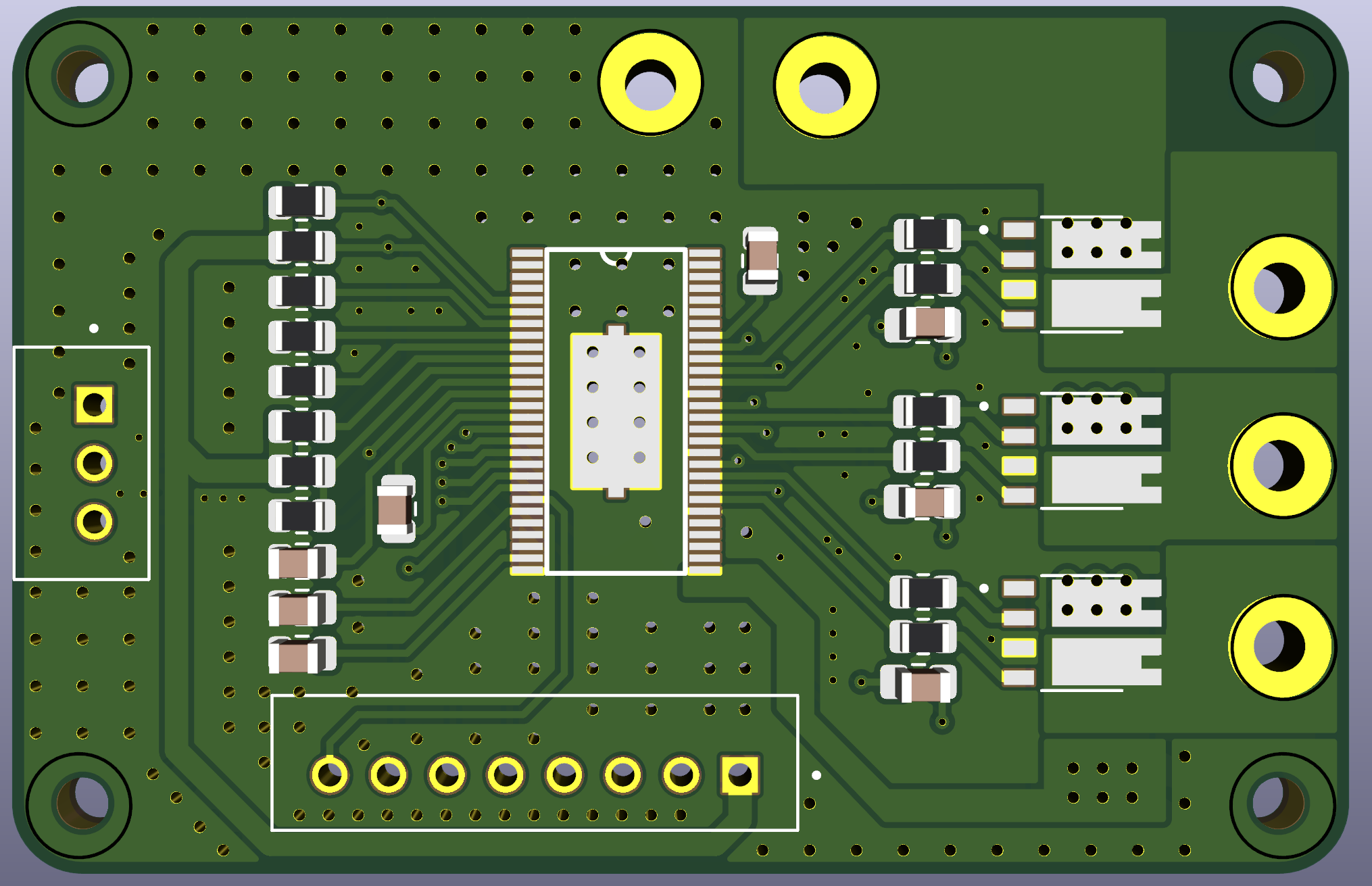
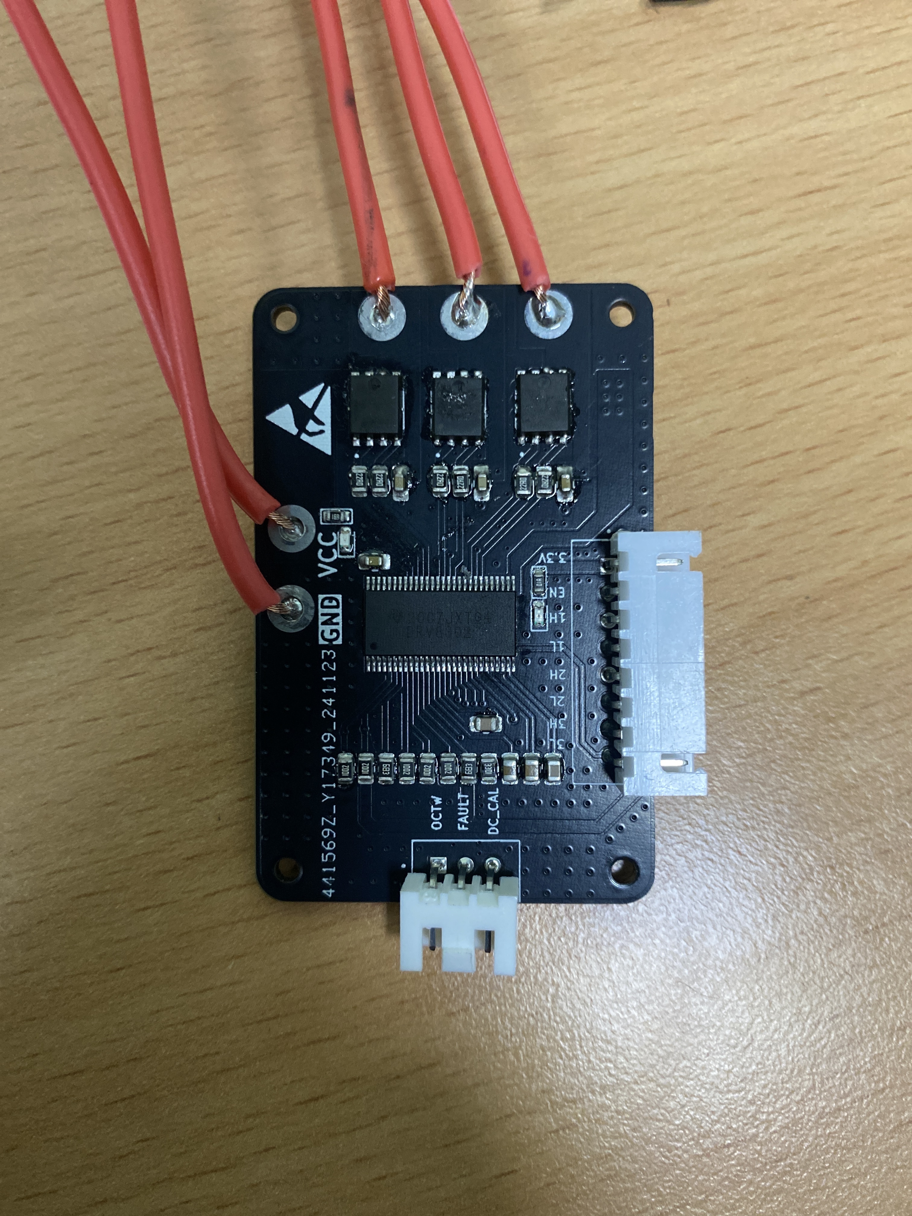
First pcb I ever designed in my life, drv8302 driver with se3082g mosfet. I will pull no more than 10A from this pcb. Any advices?

14 Answers
14Sorry for late reply, very appreciate for your advices, and I have modified like what you said. The board arrived this morning, after soldering part, I hook up the 12V supply for testing the mosfet, pull the INL_A to gnd, and 3.3V to INH_A, I expected to see 12V at the phase output? But instead it show 1.4V. Does that mean I have to provide pwm pulse INH_A?
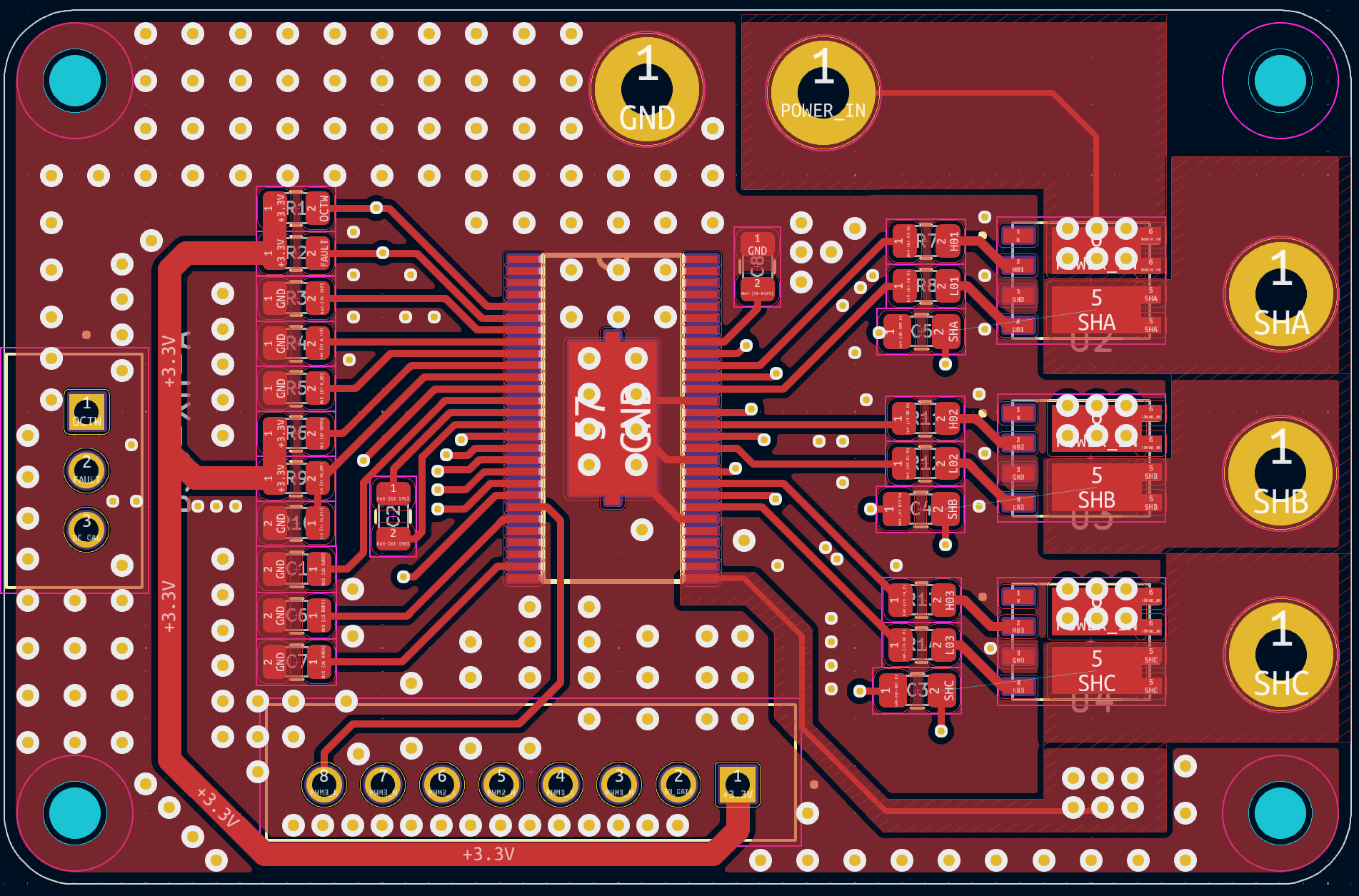
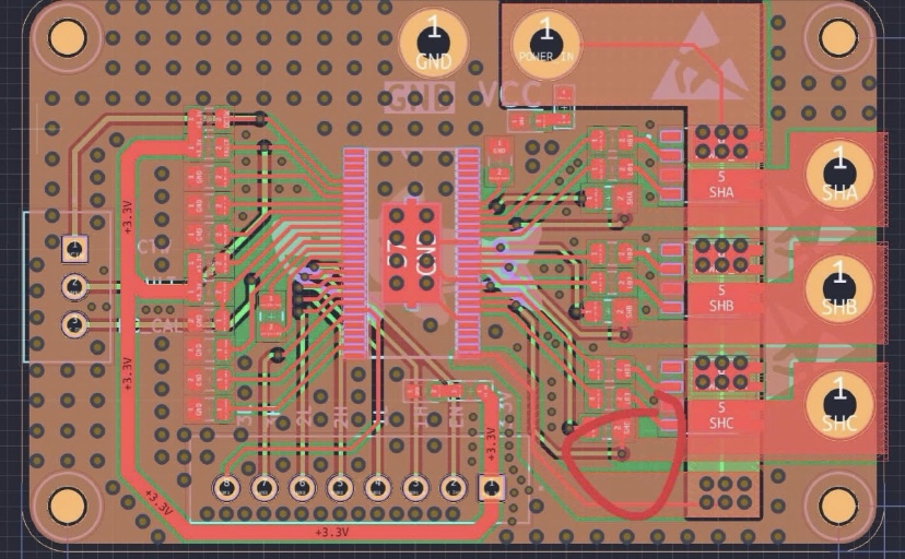
A general rule of thumb is 2A per via, so you should have at least 5 of them feeding the ground pin on each mosfet, preferably more. You’ll have to reposition the gate resistors and bootstrap capacitors to make room.
I’d recommend putting eight 0.3mm vias under the +V pads instead of six big ones. Smaller vias don’t suck up as much solder, and you can fit them entirely inside the outline of the pad. Putting them right along the edge like that could cause the chip to be pulled toward the vias by solder surface tension. Put a third row of four vias outside the pad too, for even cooler running. I’d also widen the +V track on the back toward the motor wire holes, since there’s no reason not to.
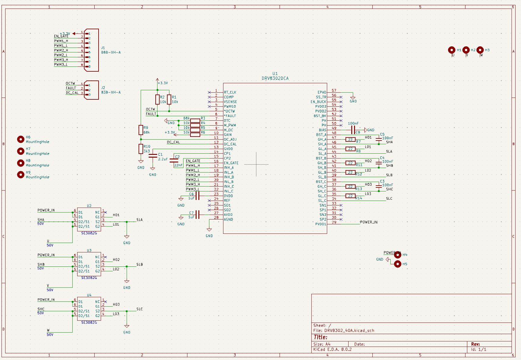
It looks like your SHx nets are incomplete, so DRC should be complaining about that. There should be traces connecting the mosfet outputs to the bootstrap capacitors/driver pins.
It won’t work without those SHx connections. You’ll have to solder some fine wire from the motor wire terminals to the bootstrap capacitors.
You may need to switch on the low side mosfet first to charge the bootstrap capacitor, then switch it off and switch high side on. But it may charge up while both mosfets are off, I’m not sure.
Oh, ok. That should work then. Try pulsing low side on first to charge the bootstrap. INH_A gnd, INL_A 3.3v. Then INL_A gnd, INH_A 3.3v. Be careful not to apply 3.3v to both at the same time. I think it has protection against shoot-through, but better not find out the hard way ![]()
If that doesn’t work, use an arduino or whatever to give it proper complementary PWM on INH_A and INL_A with duty less than 100%.
And if that doesn’t work, then you’re in the same situation I am with Gooser. I still haven’t gotten the high side mosfets to turn on properly.
very sorry for late reply, somehow when I connected my bldc motor to the output of the board, the outputs worked normally, and I can fully control the voltage outputs using complementary pwm. When I disconnect the motor, non of the outputs work. Is it normal for a mosfet?
You should use a PWM signal of around 95% duty cycle, not 100%, otherwise the bootstrapping circuit won’t work. Although the DRV 8302 may take care of this internally, not sure.
It’s strange that you can’t detect the voltage with the motor disconnected, but maybe it’s another protection of the driver? Is it a problem for you, do you need the driver to work with disconnected motor?
Regarding your schematic, I’d say you should add some bulk capacitance and some decoupling capacitance… I’d expect the driver to work better with that…
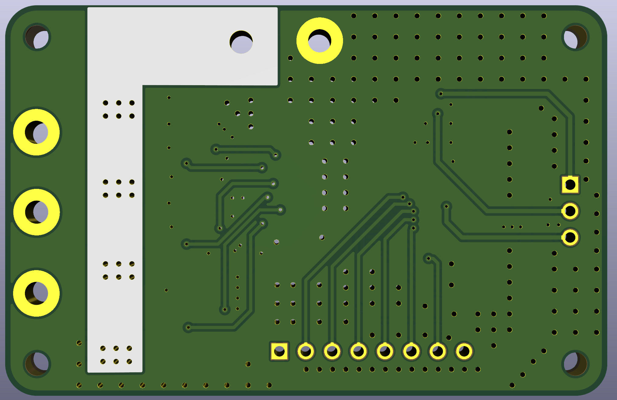
Regarding the layout, I have the comment that you have very many GND vias in some areas, but maybe should add some close to some of the signal vias.
I have made some tests, and figured out that mosfet only output if there’s load connect between 2 of the output phase (I connected a shunt resistor between two of the mosfet outputs and it worked). My intention is to control bldc motor so it’s okay. I just want to know why it happen, maybe I have missed some part in the drv8302 datasheet?
Okay I have done more test, and somehow got 2 of the outputs work normally without having to connect any load or motor. I can’t figure out why but I think there’s something relative to charging the bootstrap cap. How can I correctly charge it? I try keep the input of the low side mosfet high and the input of the high side low, but it not work.
I don’t know, but please keep me updated on your investigation. I tried Gooser with a motor connected again and still no go. Also tried touching a resistor to two of the mosfet outputs and that didn’t make any difference either.
I have posted a thread about my issue on ti support forum. In the meantime, I am planning on making another driver using drv8320 ( probably base on powershield project) or drv8300? Any recommendations that is popular and have high chance to success?
Sometimes it just worked, but almost every time its not. Im too dumb to figure out anything wrong, or maybe everything is wrong? . @Valentine greatly appreciate if you could take some time to look at my schematic and layout.


Can you give us a bit more info about what did exactly happen when it did not work ![]()
FYI we may have narrowed down the problem to a bad batch of SE3082G https://community.simplefoc.com/t/gooser-a-4-in-1-lepton-derivative/5325/74
My working Leptons were from the tail end of the previous reel. Since then, Antun, you, and I have all bought from LCSC’s current reel and had trouble. You’ve done the best if you got a motor to move in your Dec20 post, but it sounds like it still never really worked properly?