Why are some outrunners sensor-able, and others not

Ok, this is a question about motors themselves, rather than the simpleFOC library.

I’ve been doing some testing of FOC concepts with drone-style motors in the approximately 1000kV class.

I’ve noticed that a hall latch sensor (AH3772-SA-7 or TLE49 or similar) placed beside the spinning outrunner rotor will detect the magnets sweeping past for one of the motors I’ve worked with, but not for another.

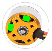
The motor I can sense the magnetic fields for is like this:
https://www.amazon.co.uk/Brushless-Outrunner-Multi-Copter-Quadcopter-Accessories/dp/B08QZ5BXLW/
with a black corrugated casing (non-conductive when putting ohm meter probes at two points on it).

The one I can’t detect fields for is like:
https://www.amazon.co.uk/Yessetry-Brushless-Outrunner-Quadcopter-Multicopter/dp/B0BTCQXSXM/
with a shiny, and conductive by multimeter probing, metal casing.

I’m trying to develop a principle for crude position sensing which can work for a wide variety of similar, normally sensorless, motors, so I’m concerned that for some it doesn’t work.

Is this a backiron effect causing the lack of a detectable magnetic field on the outside of the silvery motor?

But in that case, I always thought having backiron was a sign of a “better” motor, whereas I’ve found the cheaper motor seems to have it and the fancier one lacks it?

For future motors I may buy, of other kinds, should I then be assuming that the magnetic fields from the rotor’s magnets will or won’t be detectable from outside?

Is there a reliable way to tell from images of the motor or specifications provided (unfortunately most sellers of these kind of drone-style BLDCs don’t really give proper specs in the descriptions anyway, and what they do give is often nonsense, confusing milliohms with megohms…) whether a motor will be of the kind which has detectable magnetic fields external to the rotor?

Thanks

P.S. just to double check my understanding, FOC is in principle all about changing the overall magnitude of the current to keep the rotor tracking 90 electrical degress behind the stator’s field? I’ve seen the really basc descriptions, and looked at details of code to do FOC, but haven’t had a “middle level” picture. Does the most basic logic possible to underpin FOC look like:

if(rotor is behind where we want it){
 increase multiplier (although not in excess of some practically set limit);
}else if(rotor is ahead of where we want it){
 decrease multiplier;
}else if(rotor is at 90 lag){
 leave multiplier unchanged;
}
Phase1pwm = multiplier*1.14*(sin((float)angle*PI/180.0)*127.5+25.5*sin((float)3*angle*PI/180.0))+127.5;
Phase2pwm = multiplier*1.14*(sin((float)(angle+120)*PI/180.0)*127.5+25.5*sin((float)3*(angle+120)*PI/180.0))+127.5; 
Phase3pwm = multiplier*1.14*(sin((float)(angle+240)*PI/180.0)*127.5+25.5*sin((float)3*(angle+240)*PI/180.0))+127.5;

That is to say, we provide sinusoidal driving (with a triple frequency SVM component to maximise the voltage difference) to control the position and speed of the motor, and we vary the current so that we are having the minimum current necessary to keep the motor going at this speed (or held at this position) against whatever opposing torques it is encountering. It is the magnitude of the phase currents (the multiplier) we vary to do this, while keeping the angle (and rate of change of angle) controlled solely by the position-time curve we want the motor to actually follow?
Thanks on this clarification also

Yes, it is thickness of back iron that determines whether the field will leak outside the motor. Less leakage is good, but there is a tradeoff because more iron at the outside of the rotor where it has maximum moment of inertia takes more torque and time to accelerate. But in my experience, more expensive motors tend to have thicker back iron, so yours is unexpected. There’s no way to tell without having the motor on hand. You can test by seeing if you can feel magnetic attraction with a piece of iron.

I always put the sensors under the lip of the rotor where they can see the magnets directly. I prefer 41E linear halls using the LinearHall sensor class in the drivers repository, since you only need two and they don’t need filtering capacitors. Plus they need 90 degree phase difference, which means for many motors such as the second one you posted which have 4 openings in the bottom, you can fit the sensors in like this without having to modify the stator mount like you do for three latching halls.
SensorPlacement

Your understanding of FOC seems to be incorrect, what you have described seems to be sinusoidal control + SVM with a speed regulator.

FOC tries to regulate phase the current in the windings to be 90 degrees offset to the rotor position, to achieve the maximum torque.To do this, FOC measures the current in each winding, does some transforms in order to calculate what the angle offset is, and calculates the voltage to be applied to the windings which regulates the current to be 90 degrees offset. FOC also regulates the amplitude of the current, which is proportional to the torque, so it allows torque control of a BLDC motor.

The reason it does this is because BLDC motors have inductance, so the angle of the voltage will be ahead of the angle of the current when the motor is rotating at high speeds. This is what FOC is trying to compensate for.

The angles used in FOC do not have any relationship to the position time curve we want the motor to follow, the current is always regulated to be 90 degrees off from the rotor position. Higher level regulators, such as the speed regulator, tell FOC what the current amplitude (torque) should be, so the speed or the position time curve can be followed. It is these regulators which check the difference between the current position and the desired position (based on speed or position time curve given). The first part of your concept code describes a basic speed regulator.

The second part of your code describes sinusoidal control, because the angle and amplitude do not have any feedback mechanism.

Andrew, thansk for that, but it has left me a bit confused:
“FOC measures the current in each winding, does some transforms in order to calculate what the angle offset is, and calculates the voltage to be applied to the windings which regulates the current to be 90 degrees offset”
Measuring the current in each winding, why? One surely knows the current in each winding, or atleast the ratio of those currents, simply from what proportion PWM is being applied to each of the motor’s terminals?

The idea, I thought, for slow speed control, is that you measure rotor angle (in terms of electrical angle for multi-pole-pair motors), and then set the ratio of the PWM values for each terminal such that they lead or lag (depdending if trying to accelerate or decelerate) the rotor’s angle by 90 degrees. Isn’t the idea then that because 90 degrees between rotor position and stator current gives the maximum torque, you can reduce the PWM on all terminals by an equal proportion if you find you aren’t needing to supply the full torque to maintain the 90 degree offset? If the concept I’ve described isn’t field oriented control, what is it, because it does have some level of feedback included (change current magnitudes when offset between stator field vector and rotor angle isn’t 90 degrees) so it’s not pure sinusoidal operation.

dekutree64, thanks for the tip about poking linear sensors in to the gaps as per your drawing, I’d been using SMD ones so this thought hadn’t occured to me. It’ll be trivial to re-arrange sensors in that fashion with through hole types. I can see how a pair of quadrature linear halls get you much better resolution than an array of staggered latching ones can, thanks.

You don’t know what the currents in the windings will be just from the PWM. There are two main reasons for this: motor inductance and motor back EMF. If you had a very accurate model of the motor, you will be able to estimate the current in the windings reasonably accurately and achieve performance similar to FOC.

The reason what you describe is not FOC is because you never measured the currents, you are just estimating them.

You are also confusing torque and 90 degrees offset. In FOC, the D current produces no torque and the Q current produces torque. The D and Q axis are 90 degrees apart, think of it like the x and y axis when you plot a graph. The D axis is aligned with the rotor field. Torque is proportional to Q axis current.

When I say 90 degrees offset, I mean that the D current will always be 0, so when you add D and Q current vectors the resulting vector will always be 90 degrees offset from the D axis.

Maintaing the 90 degrees offset has nothing to do with the magnitude of the PWM, it is related to the phase of the PWM. Think of the PWM as another vector in the previous D Q plane.

You should check out the SimpleFOC documentation, reading that will improve your understanding of the control modes a lot and it is what I used as a guide when developing my custom FOC code.

One could argue that the BEMF is directly dependent on the speed and can therefore easily be calculated. The motor inductance is known coarsely and could be taken also into account.
It would be very interesting to have a performance characteristic of at least one motor using FOC or an algorithm only regulating the load angle to 90°.
Was there anything done in this direction?

I dont’ know if any BEMF correlation was done, but there is support in simpleFOC for using inductance in the motor constructor, it can substantially help with control of some motors.