I am new to BLDC motor control, but was very excited to see SimpleFOC control smaller motors beautifully! I am hopeful that it can be used to control a larger washing machine direct drive BLDC in a similar manner.
I am looking for your opinions if you think that SimpleFOC can work in this application:
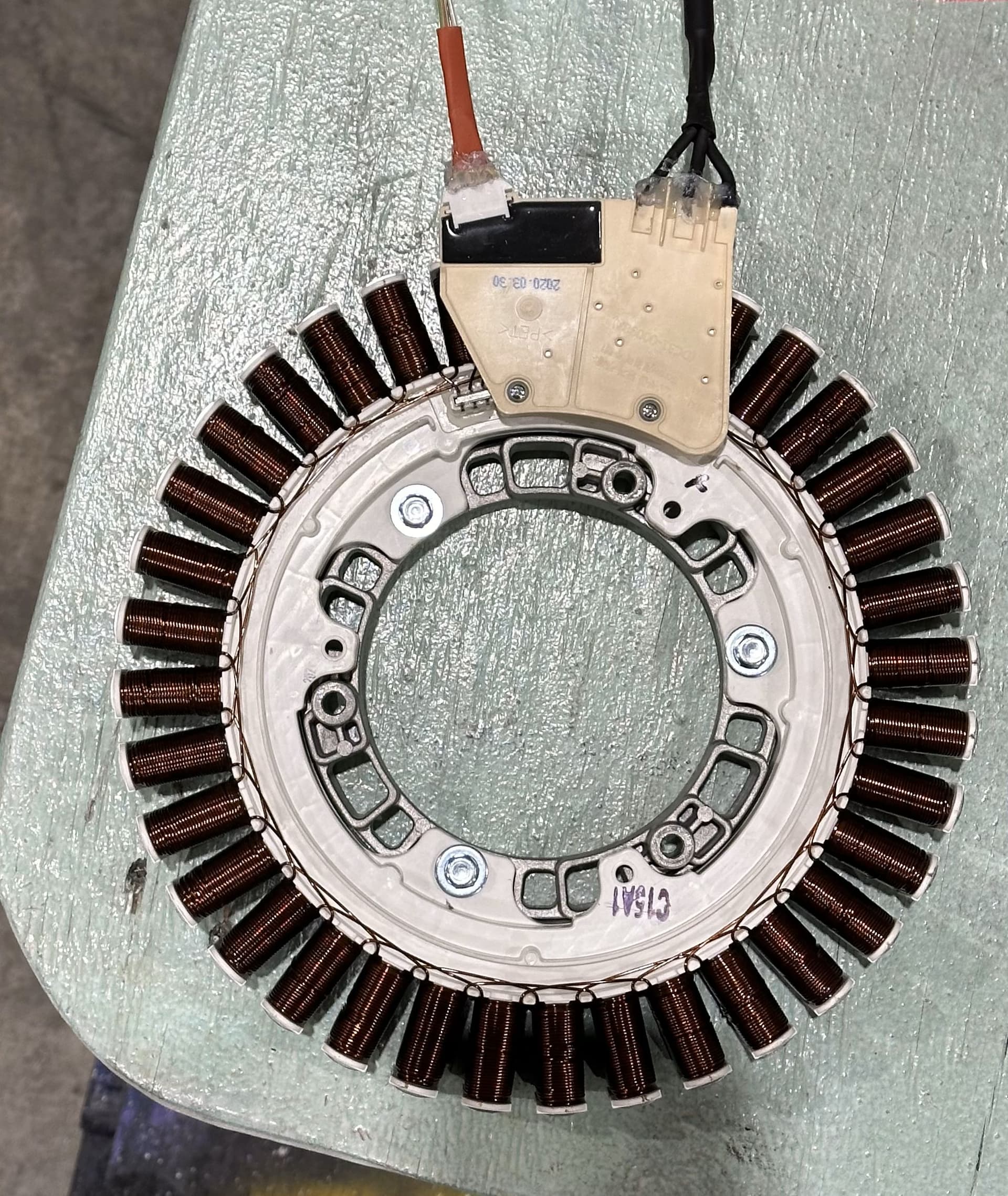
I have a spare part outrunner motor from a Samsung front loader, I picked it because it was inexpensive and appears to have very high torque to slosh a tub of water around at slow speeds. I am hoping to use it to smoothly drive and change directions of a 1.2 meter diameter 10 kilo disk turntable that will be rotating below 40 RPM. There are no published motor specs that i can find, but here is what I know:
36 poles, 3 phase, 13 ohms per phase, there is a neutral pin available if needed.
Only two Hall sensors, spaced on either side of a single pole, Vin is unknown.
Printed on the side of the rotor: DC310V 0.6HP 2.5A 1400RPM.
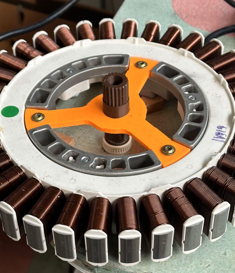
I designed and 3D printed a centering yoke to attach to the stator and a splined shaft to attach to the rotor to mate and keep an even airgap between the two components. The turntable has additional “lazy susan” bearing support to keep everything, including the rotor, level.
I connected this cheap BLDC speed controller to a 19V 10 amp laptop power supply, because that was available. I can only get the rotor to vibrate a bit and some small jerky movements, regardless of trying different combinations of motor control wires to the stator coils.
Future work:
I borrowed a 48v 5 amp power supply to see if it just needs more voltage to spin but I haven’t wired it up yet. I have the MKS Dual FOC V3.1 Plus ESP-32 controller, but I haven’t tried to flash FOC to it yet.
I am assuming that FOC needs feedback other than back EMF to do smooth bidirectional control.
Are the two hall sensors enough though?
I am guessing that the printing on the side implies that if i fed it 310 volts it would spin at 1400 RPM. Is that proportional, meaning if i fed it about 31 volts it would spin at 140 RPM?
Thank you for sharing your expertise in these matters!
I juggled some of your numbers, but they don’t match:
310V x 2.5A = 770W. That seems reasonable close to 0.6HP
But 310V / 13Ohm = 24A-ish. That doesn’t make sense.
The MKS Dual FOC plus is not a good match. I tried to run hoverboard motors with it but the fixed dead-time of the FET drivers is way to short and causes shoot-through. (like a shortcircuit)
No, they won’t be… you’ll have to use another sensor, I’m afraid. We need a sensor that reports back the rotor angle to a fairly high degree of precision. Hall Sensors in general aren’t suitable if you have a high pole count motor and want to turn it slowly in closed loop FOC. The resolution isn’t high enough.
Would you mind sharing some pictures of this motor if the forum lets you?
Presumably it is the no load speed, but as @o_lampe pointed out the numbers aren’t quite clear. Generally the relationship is linear with voltage, with the “KV rating” as a scaling constant:
RPM = V * KV
But of course if you go too low with the voltage the linear relationship breaks down when the torque isn’t sufficient to overcome the friction.
1.2m! wow, this has to be something cool!
How is this weight distributed? This kind of load attached to the rotor may have significant rotational inertia, with big implications on the system:
it can be very hard to start it moving - our normal motor calibration on startup won’t be able to deal with this
it can be correspondingly hard to stop - and may require special “slow down” handling when you want to stop, if you want to avoid big mechanical forces and voltage spikes in the driver.
while stopping or changing directions, current may flow from the motor into the power-supply. If the power-supply can’t handle this, you may need to manage this with dedicated hardware.
Is the motor already attached to this heavy rotor? If so, you will need to do some extra work to find the electrical zero point during the motor calibration.
Ideally you should calibrate the motor and find the electrical zero with no load, or very light load attached. Then our standard routines should work with this motor.
The application is a very large rotary bed 3d vase printer using a 3mm nozzle to do spiral path printing. The tool paths are of a weaving nature allowing a continuous motion back and forth radially and in the up and down direction, not a planer layer like a typical sliced 3D model.
I was attracted to FOC for its delicate motor control (especially for reversing directions) as that will be needed for short back tracking for some of the weaving paths. Most of the time the rotation is in the same direction, but back and forth wiggling of the rotation for small arcs can happen in some weaves.
3D printed brown hollow spline shaft attaches to the “upside down cake pan” rotor.
What kind of high resolution rotary position sensor might work here?
Mini hall sensors on the orange centering yoke?
I have read today that the two existing hall sensors are largely used by a washing machine to verify the direction of the rotor and maybe confirm speed.
As a first win, i would like to get reasonable uni directional speed control of this motor. Is there a SimpleFOC controller hardware that would get me started?
I still am unclear about voltage to get 40 RPM, but it might be pretty low like around 12 volts. I can see where it might draw 5 or 6 amps to start up but I would think much less to maintain speed.
I did the moment of inertia calcs for the turntable and at one point was getting around 4 Nm to change direction in 2 tenths of a second. Now that I am thinking about it I need to do some inertia calcs. Changing direction when its barely moving is one thing, changing direction at 40 rpm is another!
Is there a direct relationship between amps and Nm of torque or non linear?
In the real world it isn’t really linear, due to friction, BEMF induced by the rotor’s permanent magents when it moves, and probably some other factors.
But in theory, an ideal setup would have a torque constant K_t, and torque τ and current I related by
\tau = I \times K_t
and even in the real world the motor will behave this way for a relevant range of values.
With 10kg weight on it, you will either need a beefy driver right from the start, or you’ll have to be really careful how you try to move it. Perhaps even 1A of current at 12V would be quite enough to get it moving with no load, but with 10kg the inertia will be such that to get it moving at all you’ll either have to use FOC to ensure max torque from the outset, or drag it up to speed really slowly in open loop.
I’d strongly advise getting the motor moving with little or no load initially. To do FOC you’ll need to find the electrical zero point (calibrate the sensor with respect to the motor) and this will be hard to impossible with so much inertia.
So to actually answer your question: a simplefoc shield may move the unloaded motor, but is probably underpowered for the motor. Certainly it can’t handle 310V.
For higher power devices you might want check AliExpress, there are some DRV8302 / DRV8320 based driver boards that can handle higher currents/voltages.
Or you might want to check out the motor driver evaluation boards from either Texas Instruments or ST-Micro. They have some that can handle high voltage. If you want to use SimpleFOC, you need one that can take PWM inputs to control the gates, either 3-PWM or 6-PWM will work.
I think you’ll want an oscilloscope, most likely, before this is over, and if you intend to go up to the 300V+ you may need special probes for it.
Another option might be a driver board with current sensing, and monitoring things that way. I think you will probably need current sensing anyway in the end.
But I think you’ll want a way to look at what is happening to the bus voltage when you (for example) break the motor or change direction.
The best matching driver board would of course be the one Samsung used in their front loader. (also power supply)
We have succesfully hacked many other boards for simpleFOC, why not this one?
It’ll use IGBTs instead of MosFets, but there should be no big difference, driver-wise?
BTW: Our forum member @CNCModeller has build a polar 3D printer with stepper motors.
It’s not such a wide diameter, but rotates back and forth while printing.
Here is his YT-playlist
I purchased a spare used motor with an intact set of two hall sensors. I can see that i should have looked for an entire broken washing machine instead to scavenge various wiring harnesses, connectors control boards etc. Buying those parts separately is more expensive than buying a new washing machine!
Thank you for this link, i have been at this a while and this is the most like minded build I have seen! He is using stepper motors on his turntable, zed and radial axes, but I would like to use the large, torquey direct drive for my turn table with the delicate control FOC offers, and steppers elsewhere.
Now that i have watched the motions of his turntable I see that I am going to be between 5 and 10 RPM most of the time, so I am thinking I am going to be okay with my 19v 10a supply.
But now I need a better driver board. Is this a good choice with an external axial encoder on the end of the spline shaft? https://www.aliexpress.us/item/3256805538320526.html
plus a microcontroller running simpleFOC to talk to it?
Or how about mounting this item beneath the spline shaft?
Going from 310V to 20V will also reduce the available torque a lot. I’d go for the 50V variant and let simpleFOC reduce the max speed. That way you can push more current through the motor when required.
The rotary speed at 500mm radius is pretty high even at only 4RPM it’s around 200mm/s
Do you have an hotend which can melt filament at the rate, given that you use a 3mm nozzle?
My concern is, that you have to reduce RPM a lot and it won’t be as smooth anymore.
Both these driver boards have appeared on AliExpress fairly recently, so I have no experience to report on them. If you’re confident in embedded development these might work quite well for you if they are electrically sound and of good quality (impossible to say without ordering one). If you’re not so experienced with embedded development, these might be hard to use since I assume the documentation will be non-existent, and ODrive/VESC probably won’t offer support for these clone hardwares.
Thanks for the tip about supplying higher voltage and regulating it down. I thought torque was more about available amperage. I have wondered about the video i posted of a $20 controller slowly moving a washing machine motor that the guy can’t stall with his hands. Lower volts gives the slow speed but maybe the amps are increased to keep it torquey.
I am shooting for 200 mm a second land speed at the edge to about halfway in towards the center where most of the object walls are being woven, thats why i think i’ll need 10 rpm to keep up as the radius gets smaller. I don’t need anything close to 3D printing accuracy on laying down material from a 3mm nozzle, but I am counting on FOC letting me go slower than 4 rpm, practically a crawl going back and forth for detail work in a smooth manner.
You are right, torque and current are coupled together. But Ohms law tells us that current = voltage / resistance
With a given resistance you’d need a certain voltage to push enough current.
You still didn’t report back on the phase resistance. Is it 13 ohm?
I measured 26 ohms across two coils, so yes 13 for one coil. Having said that I came across a user manual for a older variant of a very similar motor by Fisher and Paykel. That manual said the single coil resistance was 1.3 ohms. I also measured 4 milliHenries of single coil inductance.
For sFOC only the phase-resistance is relevant. BLDC motors are usually wired in wye-config and the algorithm calculates the coil resistance accordingly.