Hey guys, I wanted to pluck this out of the sensorless drive thread because it gets too complicated in one thread sometimes.
I need reliable voltage readings for the voltages actually at the terminals of the motor. I use
  Va = driver.dc_a * driver.voltage_power_supply;
  Vb = driver.dc_b * driver.voltage_power_supply;
but the voltages are floating around up there, a nice sine wave but not centered around zero like they should be:
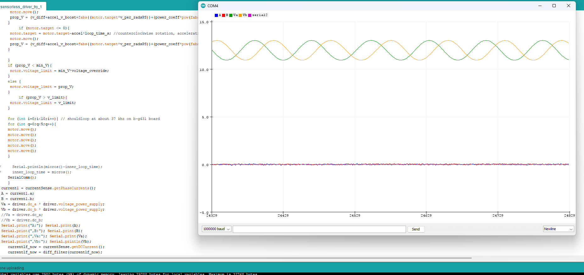
The offset appears to change, and I’d prefer to do things properly rather than just subtracting the apparent borkedness. Perhaps it’s possible that the voltages at the terminal are actually elevated like this, and that may help explain the excessive heating the board seems to exhibit even when it’s not even driving anything? IDK. They are hard to measure with an oscope because of course it’s not the actual voltage, it’s one step away from that. The actual voltage jumps around like crazy as the PWM of the inverter does it’s thing, but it gets translated by the inductance of the motor so the de facto voltage is as the pwm signal duty cycle multiplied by supply voltage indicates, correct?