Hello! I have the following question. I am trying to use simpleFOC to control a BLDC (I use DRV8305 and STM32F446) with a gearbox (1 to 30) and using 2 encoders (AS5047p) to get the position of the motor rotor and the output shaft (after the gearbox). I studied the design of various ready-made motors with gearboxes and BLDC motors from China and there were also 2 encoders on the output shaft and on the motor shaft. When trying to use simpleFOC to control this, the question arises of how to properly control the position of the output shaft. Do I really need an encoder on the motor shaft or can I get by with one encoder on the output shaft. How to properly use simpleFOC to control the motor in the presence of a gearbox. My attempts to use motor speed control and adding an additional PID controller to control the position of the output shaft showed some results, but there is a problem with oscillations and unclear position holding when applying force to the output shaft. At the same time, without a gearbox, if you apply force to the motor shaft, everything works great. I’m interested in your thoughts and maybe I’m doing everything wrong. Thank you.
Hey,
I implemented several dual-encoder systems,
and to my experience, it is best to only use the current control loop of the FOC scheme in combination with the second encoder, or so you refered to it as the output shaft encoder.
Normally applications involving the control of motor angular position would use the typical 3-layer cascaded scheme: Position → Velocity → FOC. But when another input is added (in your case, the output shaft position), I think that it’s the simplest to ditch the traditional Position and Velocity control layers and use the output shaft position controller directly as reference torque (Iq) for the FOC controller. Now I have seen some very advanced servo drivers wrap the second encoder position and velocity controllers around the 3-layer scheme, so in total 5 layers stacked, with complex feed-forward architecture, but that was totally over my head.
Regarding this:
I would strongly suggest against ditching the encoder of the motor shaft. The encoder for the motor, called the commutation encoder is prerequisite for the commutation process of the motor itself. You could derive the output shaft position from the motor position and that would be fine, but doing the opposite thing would mess up the control of the motor.
Edit: Also, I’m curious about the mechanical design of your dual-encoder system, did you use a hollow-shaft magnet for the gear box? Or did you mount the second magnet in a specific way?
Thanks for the clarification!
I used a design where the movement from the motor shaft is transmitted to the gearbox shaft through plastic gears and magnets are attached to these gears and encoders are above them.
So, what is the correct way to add additional feedback loops in this case when using FOC? Do I need to use additional PID solver objects for velocity and position? And also add low-pass filters?
In general, the idea that a second encoder (on the output shaft) is required initially seemed necessary to me because there is no way (probably) to determine the initial position of the output shaft when turned on and this can cause problems in positioning (as it seems to me).
And there is another question. Using only the encoder readings on the motor shaft, do I have the ability to set the rotation to the desired angle exceeding the limit of 360 degrees or consisting of more than one revolution of the motor? Does the FOC take into account the history of the motor shaft rotation and will be able to return it to the initial position if, after turning more than 360 degrees, I make a turn in the opposite direction by the same angle?
To be honest, I don’t really know for sure what the correct or proper way to implement additional inputs is. So far this is how I often do it:
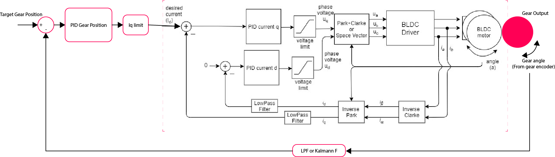
I always use the rotor encoder for the main FOC commutation, the second input (gear encoder) is fed into a PID controller whose output gets fed directly into the FOC Iq controller. You would indeed have to implement additional standalone PID for the second input, simply use the already available PID class that comes with SimpleFOC. Filters and observers really depends on your system and your desire, but SimpleFOC does offer LPF class that can be readily used as well.
Regarding this,
Yes, the library does keep track of the incremental angle of the motor (I usually refer to it as cumulative angle). In the base Sensor class, the update() method keeps track of how many revolutions the motor turned, then calling getAngle() gives you the total cumulative angle.
And regarding this:
Indeed, the point of the gear encoder is to track the absolute angular position of the gear. I have seen 6-DOF robot arms tackled this by either keeping the gear encoder on all the time using some kind of battery, or performing calibration procedure upon startup.
Now I’m not saying that you should ditch the gear encoder, I’m just trying to say that interpolating gear position using motor poisition is perfectly fine, but doing the inverse is not. If you can install an encoder on the output shaft, then there is virtually no reason not to do so, but the motor encoder is a must, always.