Hi everyone,
I am in the process of attempting to use the SimpleFOC core, with an SSI encoder on the B-G431B-ESC1 board. In order to do this, I want to use an SPI port (master receive only). This functionality I have already tested and confirmed working on a different platform, so it is just a matter of porting to the ESC board, afterwhich I can use it as a generic sensor for commutation feedback, which is where I ran into some issues.
In particular, I am having trouble using alternate functionalities of some pins to get the SPI and UART routed to where I want them. I will address the changes to the board for both of these seperately. The issues persist if the SimpleFOC library is not imported, and hence I am not sure if its directly related to the SimpleFOC libarary. Still, perhaps some people here might have more experience with this, or a clue on where to look next.
Details of setup:
- BLDC Motor: T-Motor GL100
- MCU/Motor Driver: B-G431B-ESC1 Discovery kit*
- Control Library: SimpleFOC
- Sensor: RLS AksIM-2 64mm SSI 20-bit absolute position sensor
- Software suite used is visual code with platform.io, installed as per instructions on the SimpleFOC website: PlatformIO | Arduino-FOC
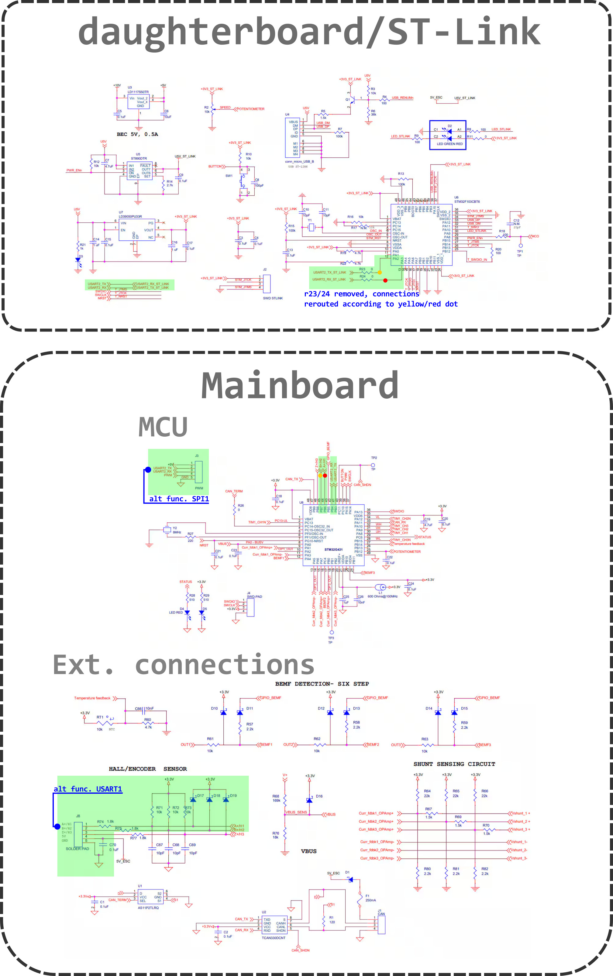
*(For documentation/schematics see bottom of the post)
USART
Normally on the board, USART2 is used to communicate with the ST-Link and outside world. These are hooked to pin 41/42 (PB3/PB4), and routed directly to the output connector J3, and to the ST-Link through R23/24.
The alternate function for PB3/4 is the SPI bus, which I want to use for SSI communication, hence I need to reroute USART to communicate with the outside world.
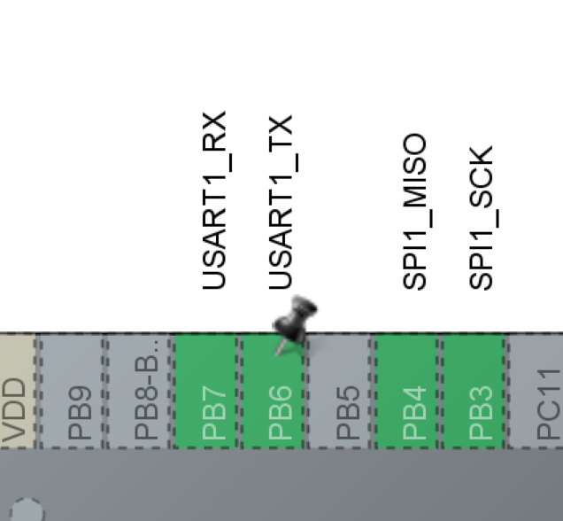
Most convenient for this, are pins PB6/7 [p# 44/55] [USART1 TX and RX respectively]. Their default functionality is hall sensor input reading, for which they are directly connected to soldering pads J8 (PB6 → A+/H1 and PB7 → B+/H2). They have a low-pass filter and some clamping, which shouldn’t pose a problem for UART implementation.
Thus to enable the hardware to function properly, R23/24 are desoldered, and A+/B+ of J8 are connected to the ST-link side of these resistors (connecting USART1 with the ST-Link). A+/B+ are routed also to the cable which is used to send/receive commands. The connection of which is verified by using PB6/7 as GPIO and sending out some signals.
I can instantiate a HardwareSerial object in different ways, call the .begin() function with appropriate baudrate (115200), but as soon as I have a .print or .printf in my code it freezes up.
If instead I instantiate the hardwareserial on USART2, it does seem to work properly (to those respective pins).
Normally I expect this behavior if you attempt to instantiate a HardwareSerial object with pins who do not possess USART functionality, however, PB6/7 definitely are able to do this (see CubeMX screenshots below).
SPI/SSI
As discussed above, PB3/4 have an alternative function for SPI (both SPI1 and SPI3). These are wired directly to connector J3, so no additional rewiring is needed. USART2_TX then becomes SPI1/3_SCK and USART2_RX becomes SPI1/3_MISO.
SPI settings are 400khz, mode0, MSB first, but I believe these are not very relevant for the problem at hand.
The port can be instantiated and setup with beginTransaction(…) and begin(), but as soon as any attempt is made to transfer bytes over the port, it freezes.
Here again I expect this is PB3/4 are not capable of SPI functionality, but they definitely are. See the following screenshot of CubeMX:
(Note that SPI1 and SPI3 both can use PB3/4 as SCK/MISO.
I am not sure if this is a hardware or software issue, any feedback on what to try next would be extremely appreciated.
Below I have included a minimum (not) working software example. The board happily blinks its LED, unless one of the “”// IF UNCOMMENTED FREEZES HERE" lines is enabled (which either attempts to use the USART or SPI port).
////// LIBRARIES
#include <Arduino.h>
#include <SPI.h>
#include <SimpleFOC.h> // Not necessary for this code

////// HARDWARE CONNECTIONS
/// SPI/SSI
// SPI port connected to the SSI absolute encoder
#define PIN_SPI_MISO          PB4 // Alternate pin functions, normally PB4 is connected to USART2_TX
#define PIN_SPI_SCK           PB3 // Alternate pin functions, normally PB3 is connected to USART2_RX
SPIClass SPI_SSI(PNUM_NOT_DEFINED, PB4, PB3); // we skip mosi, only use miso and sclk (uint32_t mosi, uint32_t miso, uint32_t sclk, uint32_t ssel = PNUM_NOT_DEFINED);
// Tried variations:
//SPIClass SPI_SSI(PNUM_NOT_DEFINED, PB_4, PB_3);
//SPIClass SPI_SSI(PNUM_NOT_DEFINED, PB4_ALT1, PB3_ALT1);
//SPIClass SPI_SSI(PNUM_NOT_DEFINED, PB4_ALT2, PB3_ALT2);

// 400khz -> Max ~8k samples/s (max allowed by sensor is 500khz) ; Mode 2 = clock pol 1 CPHA = 0 -> Because of hardware inversion with a not gate, we want clock pol = 0 -> cpol0 & cpha=0 -> mode 0
SPISettings SPI_Bus_Settings(400000, MSBFIRST, SPI_MODE0); // uint32_t clock, BitOrder bitOrder, SPIMode dataMode

/// USART/SERIAL
const uint32_t SERIAL_BAUD = 115200;

// PB7 alternate function is USART1_TX, normally connected to B+/H2 (GPIO) -> Using PB7 as GPIO can see signals at pin
// PB6 alternate function is USART1_RX, normally connected to A+/H1 (GPIO) -> Using PB6 as GPIO can see signals at pin
HardwareSerial serialPort(PB7, PB6); // (PinName _rx, PinName _tx, PinName _rts = NC, PinName _cts = NC);
// Tried variations:
//HardwareSerial serialPort(PB7_ALT2, PB6_ALT2);
//HardwareSerial serialPort(PB7_ALT1, PB6_ALT1);
//HardwareSerial serialPort(PB_7, PB_6);
//HardwareSerial serialPort(USART1);


////// FUNCTION DECLARATIONS

////// INITIAL SETUP CODE
void setup() {

    pinMode(LED_RED, OUTPUT); // Set board LED for debugging
    digitalWrite(LED_RED, HIGH);

    // Initialize the SSI/SPI port
    SPI_SSI.beginTransaction(SPI_Bus_Settings);
    SPI_SSI.begin();

    // Serial port initalization
    serialPort.begin((unsigned long)SERIAL_BAUD);

		// Simplest type of SPI transfer, a single byte
    // uint8_t temp = SPI_SSI.transfer(0xFF); // IF UNCOMMENTED FREEZES HERE

    digitalWrite(LED_RED, LOW); // Toggle LED
}

////// MAINLOOP
void loop() {

				// Periodically send a message
				// Confirmed working with HardwareSerial serialPort(USART2) on different USART pins, always freezes with USART1 (PB6/7) in any configurations
       // serialPort.printf("hi\n");  // IF UNCOMMENTED FREEZES HERE

        digitalWrite(LED_RED, !digitalRead(LED_RED)); // Toggle LED, to detect freezing
        //digitalWrite(PB3, !digitalRead(PB3));
        delay(100); // Poll at ~10hz
}
In summary, does anyone have experience on getting alternative SPI/USART ports (in particular SPI1 and USART1) working with the G431B-ESC board? Or any other pointers as to what is wrong, or what I might check next?
Thanks a lot in advance.
PS: Apologies for the lack of links and images in the post, apparently new users can only attach a single piece of media and 2 links per post, hence I will add these as a reply.