i am trying hard to find out how current limit of 60A ± 2A is arrived.
1st question: When current limit is referred i always assume it at the inverter output or the AC side. Am i correct?
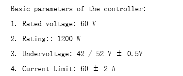
2nd Question: 60A is arrived like the minimum battery voltage is 42V, Wattage is 1200. Hence the maximum current is
Current limit = 1200 / 42 = 28.57 A is what i could get. Please help me how 60A is arrived?
An electric motor has a continuous power rating, but for short times it can be overloaded upto 3 times the rated power limit. ( during startup for instance). A controller should be able to handle that.
You just have to ask the manufacturer. If there is a standard they won’t respect it for cheaper units, and the number might only be an estimate or total bunk. If it was me I would make it the average current the output can provide, total.
only for 48V. It says rated input voltage is 48V and max input current is 15A. So, the maximum input power
Pin = 4815 = 720W
The maximum output current is 55A, so it is line current my calculations according to a reference document from TI
The voltage applied on the Inverter side = VDC/sqrt(2) = 48/Sqrt(2) = 33.9V
Il-l current_peak = Poutsqrt(2)/sqrt(3)Vl-lCos(Phi) = 240/(33.91.730.9) assuming cos (phi) = 0.9; Ans = 6.4 Amps. I am no way near the answer of 55A. Please help to interpret these values.
No, they would both be maximums. You can’t exceed the power rating. I don’t know why the current rating would go up at lower voltages, but that is what is implied if the voltage and current ratings are as stated. Or the current rating may be momentary only, while the power rating is continous. It’s not a good way of specifying things, I also compain about how motors come with voltage ratings. Usually ratings assume a certain typical usage scenario which you have to know or find described in an application note somewhere.
There is a phenomena that occurs in stepper motors where the coils act as step down transformers, this leads to higher currents than the input currents flowing through the coils. This may be what they are talking about with the output current. The current flows in one lead of the inverter and out another. I don’t exactly know how it works but I know it’s a thing with stepper motor drivers.
Is the below configuration possible, i have connected the DC power supply of 48V and the motor controller works in the operating range of 35V-72V and the motor is 60V.
Do i need to connect the battery of 60V and above or still the motor can work?
A 60V battery would also be in range for the hardware. I would not go much higher than that, since the driver limit is 72V. Battery voltages aren’t exact, so depending the battery chemistry and level of charge the voltage could exceed the rated 60V… so better to leave some safety margin.
I have a doubt here if the input voltage is 48V then the maximum output voltage of the controller is 48/Sqrt(2) = 33.9 Vrms But the motor specifications it works at 60V, so how does it work? Am i missing something?
Normally the specs give the number for the maximum voltage or for typical operating conditions…
A BLDC will usually run at far less than the specified maximum voltage. But of course the current and therefore the torque will be lower, the lower the system voltage.
At some point the voltage is too low to generate enough current to overcome the static friction and then the motor won’t start. But above this point and below the maximum you can choose any voltage compatible with the rest of your hardware.