Uncharacteristic problem - PWM high/low modulation on STM32G431KB nucleo possibly causing shoot through?

Yes, this is enough to monitor the PWM signals, which are only in the range 1-100kHz normally.
I use the cheap ones all the time for this, with the free PulseView application.

Ouch! For testing, which motor are you using, what’s the resistance? Have you set a driver.voltage_limit and motor.voltage_limit? When doing first tests, try to set these limits (and also the PSU itself) conservatively (i.e. low!) to help prevent things getting damaged.

Do you have pull-down resistors on your drivers’ and or MOSFET’s inputs? These can be important to keep the driver in a defined state when the MCU is starting up.

Are you working in ArduinoIDE or PlatformIO?

Normally, the G431 is well supported, and the PWM generation should work fine. Of course, dead-time could be too low at the default setting, you can try to increase it to see if this helps (driver.dead_zone = 0.1;).

@Valentine @runger i’m sorry for the delay, i ordered a logic analyzer to present some accurate charts.

The motor is a 250W, 36V, 15 pole pairs, electric scooter motor. I dont have a motor with less power so im trying to test carefully. The meassured phase resistance is around 0.6 - 0.7Ohms.

I have 10k pull-downs on HO and LO driver outputs to the MOSFET gates, and i am using ArduinoIDE

  1. The circuit schematics is basic, i wanted to add hall sensors for position feedback later. Right now i am powering the Nucleo from USB, for easier testing, but it is connected to common ground. The drivers also dont have a voltage regulator yet, so they are powered with the same voltage as the motor. That’s why im not testing above 20V. As for now, the schematics looks like that:

  1. With the logic analyzer I measured the PWM on the input of the drivers HIN, LIN.
    This is the chart of the signals, in HIN/LIN order, phase A is starting from the top.
    The program was basic, with no serial com. The test voltage was 18V.

My knowledge about PWM modulation schemes, is not the biggest, but in my opinion it looks correct. No shoot through caused by the PWM.

  1. I also analyzed the output signals from the drivers outputs HO, LO. Becouse if the inputs are ok, then there must be something wrong with the outputs themselves. The signals were meassured directly on the MOSFET gates. All the parameters were the same as before.


this is the whole view


this is more close up

Although I dont have enough knolwedge, these signals look very weird. For example, almost all of the High Side MOSFETs, are ON at the same time. And at the same time all of those High side MOSFETs are ON, all of the Low side MOSFETs are also ON.

  1. The setup:

I know it could be done much better and please excuse my solder work, it was already resoldered a few times. I tried to ensure everything is well isolated. There is sort of a power rail, made out of thicker wire. All the signal wires are isolated. There is a common ground point for drivers and mcu. There are 10mOhm power resistors for future current messuring, but looking like its going so far, i dont know if it will be possible to add that ;D. If i would be able to make it work, the next step was supposed to be, makeing an actual pcb out of it.

  1. In the end, i don’t understand why the output signals from the drivers look so broken. It looks like the problem is connected with the drivers but i don’t know what it is. I never managed to make the ESC work with the ir2103 drivers. Not even one turn of the motor.

Thanks for this extremely detailed and careful error report :slight_smile: that’s awesome.

The PWM does indeed look correct, IMHO.

This is normal. The PWM signals should all be centre-aligned if you’re using pins belonging to the same timer. So whatever on-time the phase has occurs with the same centre-point, and it’s normal the FETs are all open at the same time.

This is not normal, and it may not happen - otherwise you have created :“shoot-through” - a short circuit between VS and GND via the two FETs. Currents will go very high and things will burn.

Bit I think looking at the datasheet is clear why:

The low-side input of the IR2103 is labeled LIN with a bar on top, i.e. nLIN - this means the polarity of HIN and LIN is opposite, and LIN logic is active-low, i.e. a low input to LIN switches on the driver.
Ouch.

In the datasheet they describe this in words as:

  • High side output in phase with HIN input
  • Low side output out of phase with LIN input

What this means:
You need to drive the low side of this driver using active-low polarity. This is not the default option for SimpleFOC, but we recently added support for it on STM32 (which is what you’re using, lucky you :-D).

So to use it, you can:

  1. Use the dev branch of the library from GitHub. You can do this by replacing the library in your Documents/Arduino/libraries folder with a git clone from the dev branch.
  2. Add the option -DSIMPLEFOC_PWM_LOWSIDE_ACTIVE_HIGH=false to your build. In Arduino IDE it isn’t super-easy to add build flags, but you can find instructions on-line.

If you’re successful it will change the polarity as needed, and you should see that the high and low side FETs don’t open at the same time any more.

3 Likes

Thank you for help @runger, relieved to finally know what was the problem. A painful rookie mistake ;D.

I’ve read about what you told me to do and tried out a few options. But it didnt work as expected, so most probably i messed something up again.
So what i did was

  1. I cloned the SimpleFoc library dev branch from git hub to my pc with Git Bash
  2. Replaced the library files in the Documents/Arduino/libraries folder with the ones i cloned
  3. In the same folder as my global platform.txt file, i created a new file platform.local.txt
  4. I copied the contents from the platform.txt to platform.local.txt and used the property “compiler.cpp.extra_flags = -DSIMPLEFOC_PWM_LOWSIDE_ACTIVE_HIGH=false” to add the option in platfrom.local.txt
  5. Restarted Arduino IDE

In the end it didn’t work so i definetly messed up. The whole process seems a little unnecessarily complicated on ArduinoIDE. Is there a simpler, more reliable way of doing it? What if i would switch to PlatformIO? At first i was going to switch drivers, but the ones i would need, are a bit hard to get at the moment.

The way you describe your steps, it all actually sounds quite correct, so I am not sure why it would not work.
But as you say, working with ArduinoIDE is very complicated once you need things that aren’t built in…

Personally, I much prefer PlatformIO, but this is because I am used to complex IDEs and software development from my professional life. Other users find it overwhelming and confusing compared to Arduino IDE. Its a very personal choice, and hard to say what each person will find easier…

But in platformio these kind of things are much easier. The build flags can just go in your platformio.ini file, and the library can be git-cloned into the lib subfolder of your project… customization of the build process is more “built in” in platformio.

I wish I could say what the problem is in ArduinoIDE - what you did sounds correct, so its probably down to some detail… it should be possible to get it working in ArduinoIDE as well.

Sorry I can’t be of more help on this, and I do hope you find the issue soon!

Hi @runger , you think your suggestion from this post (Link) would work for this driver also? (using 3-PWM will enable pins?) The only thing is I don’t know if SimpleFOC will switch-On and switch-OFF the enable pins along with the HIN pins simultaneously?
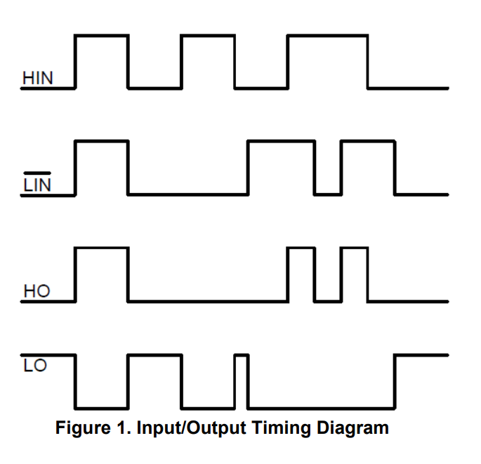
Below is the timing diagram of the IR2103 for reference.

I used 3pwm mode with such drivers. Simply connected the output of each phase simultaneously to both driver inputs. A high signal opens the upper shoulder, a low lower one. I’m not an electrician, maybe it’s not right, but it works

1 Like

Hi @nikolaewich1988 , I think that’s the right way.
I’m trying to see if it’s possible to do the same through the MCU (supplying HIN and LIN*(_bar)) simultaneously through SimpleFOC (within the program).

No, it won’t, so this won’t work unfortunately.

This suggestion will work, I think. But check the currents carefully if you can. The driver has interlocking protection, but not dead-time insertion. So if I understand how it works correctly it really will switch both FETs at the same time. But FETs take some time to open or close, so in this case there can be a short time when both FETs are simultaneously open. It depends on the FETs, the drive voltage and other factors…
This would be the advantage of getting the 6-PWM working, because it will do dead-time insertion and thereby ensure that only one FET is open at the same time…

@runger Hello. I use eg2133 and used to think it had its dead time. Am I wrong?


My Chinese is not so good, but I would say yes, from picture 7-3…

But I meant @mizzi_labs , who is using IR2103, which I don’t think does it.

the ir2103 chart also has a dead time?

You’re right, and in this case the idea to use 3-PWM will work well!

great, thanks @runger, will try it out . Using 3-PWM instead of 6-PWM, the main draw-back is the control over dead-time is now relied upon the gate-driver only, right? Anything else, we may loose by using 3PWM instead? sorry for our beginner level questions. but truly appreciate all your efforts for this community.

That’s one drawback, but only an actual problem if the dead-time doesn’t suit your needs (FETs).

In your particular configuration with both inputs controlled from the same signal it actually also means you will always have one FET open, you can pick between high and low side, but one will be open (except briefly during dead-time). This means you can’t do things like switching all the FETs off for coasting or BEMF based commutation - but SimpleFOC doesn’t support these things yet.

1 Like

Got it, thanks for the detailed explanation.
That was one thing I was worried about, if we’ll loose any performance by using 3PWM over 6PWM. Coasting and BEMF are not part of my scope yet. So, 3PWM works great!
Appreciate all the help.

For drivers which include enable, does simpleFOC allow you to use this for the hi-Z state in combination with the active high/low control pin? Control-wise it still comes out to needing 6 pins, but there are some drivers (like single half bridge gate driver) where this is required.

Edit: sorry, maybe that was too vague. I mean to use 3x of some chip like this, in place of a single-chip driver.

Yes, @VIPQualityPost , we support such drivers.

You can use 3 enable pins in the constructor to BLDCDriver3PWM, like this:

BLDCDriver3PWM(phaseApin, phaseBpin, phaseCpin, enableApin, enableBpin, enableCpin)

so you can have separate EN control for each phase. Then you can use 3-PWM but still have the option to close both FETs of each half-bridge via its EN signal.

1 Like

In that case is there any difference between 3pwm and 6pwm other than the mcu is not in control of the dead time insertion? Well, it still has some control, but it doesn’t know about the additional insertion by the half bridge driver? I guess you can still configure dead-time in the software anyway so you can compensate.

Additionally, does this enable pin need (should?) to share the timer with PWM pin?

Hey, yes, but these are generally more “advanced” type motor control scenarios that we currently don’t yet support in the library. This would include things like:

  • implementing plug braking vs. coasting
  • implementing braking via external resistors
  • implementing regenerative battery charging
  • implementing other switching schemes, such as space-vector switching

no, any output capable digital IO pins can be used as a the enable pins. This makes 3-PWM “easier to use” than 6-PWM, where the pins should ideally all come from the same timer. It may turn out that not having the EN pins on the timer doesn’t work well for BEMF sensing though, once we get to implementing that… lets see :slight_smile:

1 Like