Typo in the drawing driver code docs

There seems to be a problem on this page:

I realized only after buying boards that that system shown can’t work for the purpose. You can’t practically use N-channel mosfets on the high side like that, from what I read. N-channel mosfets are turned on by a positive on the gate, relative to the drain. It has to be like 5 volts or something higher at the gate than at the drain. When the drain is connected directly to ground, this works fine.

But the motor is in between ground and the drain, as soon as the mosfet turns on, the voltage on the drain would get close to the positive supply voltage, because the voltage is reduced by however much the resistance the current has crossed divided by the total resistance. The resistance of the transistor would be very low and the coils of the motor at least 10 ohms, not even considering induction.

I don’t know how it even stays on at all, I guess it achieves an equilibrium where the resistance of the transistor is such that the voltage at the drain is just enough to only just keep the transistor partially on, in a state of undesireably high resistance but not extremely high and not extremely low. This obviously implies that the voltage drop across the motor is way less than the intended voltage, and the transistor will get hot, possibly too hot. I guess if the motor was held still and the system allowed to achieve equilibrium it would be supply voltage minus very approximately the 5 volts (which varies between transistors).

This definitely is not going to give a nice sine wave, it will totally mess up the voltage from the system.

My understanding is rudimentary, I apologize, and I know, but who else would get trapped by such a problem. I was about to chop up the boards I bought to extract the N-channel mosfets and rewire them for use on the high side (the board wiring confines them to use on the low side when they are as they come). Fortunately I realized this is not going to work before I sacrificed that time and money…
@Anthony_Douglas

Please do not get frustrated. Could you please explain a little more about your problem? I don’t believe there is an error in the documentation. Where did you see that? It was a bit unclear from your explanation. Also, any schematics of what you are doing will help.

Cheers,
Valentine

PS I re-read what you posted, I believe you confuse the sine wave with the on/off PWM modulation of the wave. The mosfets are only turned on or off, they do not work as traditional transistors, for example an audio amplifier, do. You build the sine wave by modulating the timing of the PWM on/off chopping of the voltage over time.

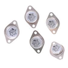
Did I clear your misunderstanding? There is a dramatic difference between a MOSFET and a traditional transistor like this one:

image

The audio transistors work in the middle ground between fully on and fully off. MOSFETs only work as on and off. If you try to drive a mosfet like an audio transistor it will literally explode and burn.

Please let me know if I misunderstood your understanding and what are you trying to acheive.

Also please don’t get hurt.

Thanks Valentine, I apologize if I sound upset. These are not good times for me in general, and partially because my open source erv project is not going well.

Mosfets will fail to turn fully on or off if they gates are not driven to the right voltage. They do have region where they do act as amplifiers, the bare transistors. When driving a motor, of course you want to keep it out of that range.

I understand the mosfets get turned on and off with a PWM signal, but the signal is then supposed to be filtered and smoothed, causing a good approximation of a sine wave for the current flow into the phases of the motor, as a result of the induction of the motor winding.

This is very important for FOC, is my understanding. The sine wave is the ideal way to drive the motor, giving the smoothest motion. It’s what gives a smoothly rotating magnetic field.

The assumption in the precomputed table for the PWM values is that the Mosfet turns fully on and off as described. I tried this with an L298 recently, and it couldn’t give a smooth waveform, I posted about that in the forum, if you are curious, search “jerky motion with arduino nano and l298”.

If one of the the mosfets isn’t fully on or off, it will change the relative amount of current flowing through any given phase at any given time a great deal. I observed this myself directly with the arduino and l298 setup, I put some potentiometers adjusted to 3 ohms in front of each winding so I could measure the current with an oscilloscope, and one of them got bumped slighly by accident, changing its resistance to 6 ohms. It caused the current waveform on the oscilloscope to get totally messed up, even more than it was before, and the motor to become even more jerky.

With some kind of closed loop system that monitored current flow and compensated the pwm at any given instance, this could perhaps be corrected for.

But the diagram shown in that page is not an acceptable way of driving a load with an N-channel mosfet for the reason I described. There are many resources that point this out. You have to have P channel mosfets on that side, unless you use a driver voltage which gives a higher voltage at the gate than the source voltage. Here for instance : design - Is it possible to build an H-Bridge with only N-MOSFETs (and these other components)? - Electrical Engineering Stack Exchange

I’m still trying to understand your problem. In summary, are you trying to build a half-bridge with two N-channel mosfets without a high side driver? How are you driving the mosfets?

It would help immensely if you post schematics or pictures.

You MUST use a high-side boot-strapped driver. There is no other way. By high side driver I mean, the voltage on the high side mosfet MUST be the motor power voltage plus at least 5 volts. So if you supply 12V for your motor, you MUST drive the sigh side mosfet with 17 volts. The low side you can drive with 5 volts. It’s basic physics (coulombs law).

That’s what I am saying. That is not shown in the schematic on the page I linked to. It just shows the pwm going in, straight to the mosfets. That can’t work. That’s what I was going off of when I decided to buy these driver boards, these ones https://www.amazon.ca/gp/product/B07YKFR72R/ref=ppx_yo_dt_b_asin_title_o01_s00?ie=UTF8&psc=1

I see. The page is an educational conceptual schematics, not even coming close to a blue-print for building a BLDC driver. Hardware design of BLDC drivers is completely out of scope here. This is only targeted at people to conceptually grasp the very basics.

Just buy a driver and bob’s your uncle.

Hey @Anthony_Douglas,

There are many BDLC drivers that use only N-channel mosfets, but yeah there is definitelly some mode logic in between the PWM signals and the mosfets themselves. If you look only the image itself it would not be obvious, I agree.
As Valentine said, these drawings are not schematics and they are there just to enable people to better understand what are different code parameters in the code. I have first put just a simple switch image but then in my drawing software I’ve found something that resembles a transistor so I’ve put it instead. I’ll change the draving to use a P-channel transistor.

The same as the voltage limits drawing shows the sine waves even though the real voltages will be square.

These schematics are in the part of the docs which is called writing the code and particularly the BLDC driver code. It is not there to guide the design of the driver in any way.

If you are designing your own driver using only the mosfets, check this link also. It might be helpful:

Now, I feel like we’ve started off on a wrong foot with you @Anthony_Douglas. I just want you to understand that the SimpleFOC is a community project. It is not a company and has no employees. Nobody works on this project full time or makes money on it. We are all working on it in our free time and because we like it.
SimpleFOClibrary is an arduino library, that being said it is not in any way a production software. It can be, and many people have used it already in their solutions, but it is on to you to make sure it fits.

So I understand that some parts of the SimpleFOC make you angry sometimes, it also gets me frustrated sometimes. Take a deep breath and continue, the answer is probably just around the corner. :smiley:
And just remember that even though the SimpleFOClibrary code and docs seem simple maybe or similar to different software library docs, whenever you include hardware into the equation (especially this large variety of different solutions) finding a balance for a particular use-case is never easy (especially when you are searching for cheap options).

So I am sure you will find your solution and probably using the SimpleFOC but to do so, I am afraid that there is no other way than to put some more days into it and also probably some more bucks.
We will try to support you on our side, as much as the time allows us.

I do appreciate what has been done and the willingness of others to help. I am also willing to pay for help don’t get me wrong, even though I am far from mr. moneybags and don’t want to imply I am doing anything particularly profitable.

However when I look back, the barriers and difficulties are quite extensive. I have spent literally several working weeks and quite a lot of money already, with no result, although I think I am getting closer.

What bothers me is this idea that because no one is getting paid, nothing has to be done or done well. I don’t actually agree with that as a sensible approach. If people need to be paid to do good work, we should pass the hat and make that happen. But good work needs to be done. I believe in the power of engineering to improve life. That can’t happen without doing quality work, whether we get paid or not. I do a lot of mechanical open source work, for instance the greens for good centrifuge, and also my previous window mount ERV. When I do, I do good stuff.

Again I don’t want to rub people wrong way especially because I seriously am out of my depth here and need help. And maybe therefore it is foolish to bring this subject up, however it comes up when it comes up.

Fundamentally, if no one is willing to do the things that need to be done without getting paid, which is quite fair and I sympathize with, then we as a community should pony up. That’s my position. To avoid monetary exchanges and then use the no money as a reason for why nothing works is not going to improve people’s lives, as far as I can tell. Stuff has to get done, one way or another, pick your adventure and decide how, but one way or another it’s gotta get done.

To be fair, I live by this so I don’t think it’s unfair to express this idea. Again, no offense intended and I do greatly appreciate what is done and has been done by others, and I believe they should be compensated. I hope that if we do good stuff together then you will get consulting gigs and stuff at least as a reward? I seem to hear a bit of that happening already.

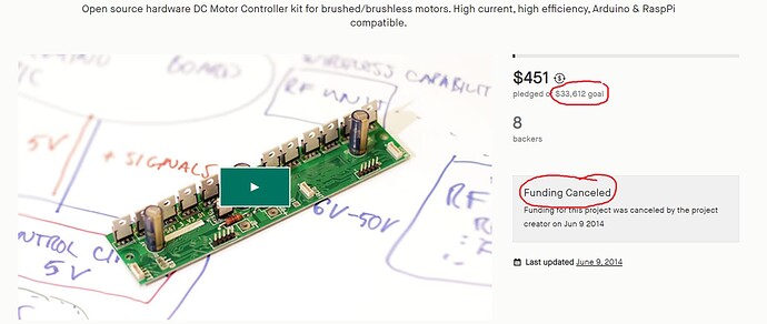
It’s a good discussion. However I’m not convinced you could find enough people to contribute to a project which is tailored to a relatively narrow case. I could definitely look into Kickstarter for example to research the possibility. Again, I have very low confidence this is going to work. First, not enough people to contribute money. Second, the engineering rates for such a specialized niche product are really high. If this is for profit you will get standard engineering rates for wherever that person is. I don’t even need to tell you Silicon Valley rates. You will get a lot cheaper rates in Western Europe and even cheaper from Easter Europe, with the lowest in India. But in my experience the development of a semi-commercialized grade board like that including testing and documentation would be somewhere between 2 to 4 months full time. Multiply by the prevailing rates for a person, say $50/hour blended rate, and you arrive at $20 to $40k including two iterations, and testing hardware. Finding people to pay this money is not realistic. This is my day job, with 30 years of work experience behind me working for the largest engineering companies in the world, and I can speak very confidently about this type of work.

Edit:

I don’t really know what to say… driving BLDCs just isn’t the easiest thing to do… I think that’s part of the reason many of us here find the problem interesting…

I quite fundamentally disagree with this. I think the SimpleFOC project represents excellent work, and part of the reason I joined it was that I felt this was a really high quality open source project, with an active and supportive community and excellent documentation.
I think we have nothing to be ashamed of here, and can compare ourselves very favourably with other projects the same size.

I think there may be scope for that, there are services that allow you to collect funding for such activities, like bug-bounty type things. But as Valentine has pointed out, I think you’d be surprised what engineering/developer time costs when you actually have to pay for it.

But if we can find backers, define some clear goals, and find someone to do the work within the budget collected, why not?

2 Likes