I’m trying to run a PMSM in closed loop velocity using the sensorless observer. If I change to openloop command MC3 and send M3.53/rads the motor spins after I give it a help to start.
When I close the loop command MC1 and send M3.53rads the motor just shakes back and forth. I’ve set PID to “0” to so I can tune via the commander. Phase current is also very low at about 70mA whereas openloop phase current is about 250mA.
The hardware is an STM32F4 and SimpleFOC shield 2.0.4
I’ve obviously got something wrong and have spent hours searching to solve this to no avail. Hoping someone can point me in the right direction.
// Sensorless FOC for STM32 and PID
#include <SimpleFOC.h>
#include <SimpleFOCDrivers.h>
#include "encoders/MXLEMMING_observer/MXLEMMINGObserverSensor.h"
// Stepper motor & BLDC driver instance
BLDCMotor motor = BLDCMotor(10, 7.26, 17, 0.016);
// BLDCMotor motor = BLDCMotor(10, 27, 17, 0.016);
// BLDCDriver3PWM driver = BLDCDriver3PWM(pwmA, pwmB, pwmC, Enable(optional));
BLDCDriver3PWM driver = BLDCDriver3PWM(PA7, PA6, PA5, PA3); // STM32
// MXLEMMING observer sensor instance
MXLEMMINGObserverSensor observer = MXLEMMINGObserverSensor(motor);
// Lowside current sensor instance
LowsideCurrentSense current_sense = LowsideCurrentSense(0.01f, 50.0f, PA1, PA2); // With these settings M0 commands now stop motor
float offset = PI/(2*10);
// commander communication instance
Commander command = Commander(Serial);
void doMotor(char* cmd) {command.motor(&motor, cmd);}
void setup() {
// use monitoring with serial
Serial.begin(115200);
// enable more verbose output for debugging
// comment out if not needed
SimpleFOCDebug::enable(&Serial);
// link the motor to the sensor
motor.linkSensor(&observer);
// driver config
// power supply voltage [V]
driver.voltage_power_supply = 20;
motor.voltage_limit = 20;
driver.init();
// link driver
motor.linkDriver(&driver);
// link current sense and the driver
current_sense.linkDriver(&driver);
// current = voltage / resistance, so try to be well under 1Amp
motor.current_limit = 1.0; // [Amps]
motor.velocity_limit = 5;
// set control loop type to be used
motor.controller = MotionControlType::velocity;
motor.torque_controller = TorqueControlType::voltage;
// set FOC modulation type to space vector modulation
// motor.foc_modulation = FOCModulationType::SpaceVectorPWM;
//motor.foc_modulation = FOCModulationType::SinePWM;
// velocity PID controller
motor.PID_velocity.P = 0;
motor.PID_velocity.I = 0;
motor.PID_velocity.D = 0;
// jerk control using voltage voltage ramp
// default value is 300 volts per sec ~ 0.3V per millisecond
motor.PID_velocity.output_ramp = 300;
// velocity low pass filtering
// default 5ms - try different values to see what is the best.
// the lower the less filtered
motor.LPF_velocity.Tf = 0.01;
// current sense init and linking
current_sense.init();
motor.linkCurrentSense(¤t_sense);
// initialise motor
motor.init();
// skip the sensor alignment
motor.sensor_direction = (offset, Direction::CW);
motor.zero_electric_angle = 0;
motor.initFOC();
//motor.PID_velocity.limit = 5;
motor.target = 0.0;
// subscribe motor to the commander
command.add('M', doMotor, "motor");
// Run user commands to configure and the motor (find the full command list in docs.simplefoc.com)
Serial.println("Motor ready.");
_delay(1000);
}
void loop() {
// iterative setting FOC phase voltage
motor.loopFOC();
// iterative function setting the outter loop target
motor.move();
// motor monitoring
motor.monitor();
// user communication
command.run();
}
Use MotionControlType::torque until you get it running. Most likely it just needs tuning of the resistance, kv and inductance parameters. And you have to copy-paste the calculation of flux_linkage from the MXLEMMINGObserverSensor contructor, otherwise changes to kv won’t have any effect. But usually the official kv value for the motor will work. Mostly it’s the inductance that needs trial-and-error tuning, and sometimes resistance.
And you have to copy-paste the calculation of flux_linkage from the MXLEMMINGObserverSensor contructor,
Does this mean I need to copy this to the main code?
The motor is an OEM Technics so I used this code to measure R and L which was different to what was measured with my LCR bridge . KV I measured the BEMF by manually spinning the motor to 33rpm
#include <SimpleFOC.h>
// Stepper motor & BLDC driver instance
BLDCMotor motor = BLDCMotor(11);
// SimpleFOCShield
BLDCDriver3PWM driver = BLDCDriver3PWM(A7, A6, A5, A3); // STM32
// inline current sensor instance
// ACS712-05B has the resolution of 0.185mV per Amp
LowsideCurrentSense current_sense = LowsideCurrentSense(185.0f, PA1, PA2);
void setup() {
// use monitoring with serial
Serial.begin(115200);
// enable more verbose output for debugging
// comment out if not needed
SimpleFOCDebug::enable(&Serial);
// driver config
// power supply voltage [V]
driver.voltage_power_supply = 20;
driver.init();
// link driver
motor.linkDriver(&driver);
// link current sense and the driver
current_sense.linkDriver(&driver);
// current sense init and linking
current_sense.init();
motor.linkCurrentSense(¤t_sense);
// initialise motor
motor.init();
// find the motor parameters
motor.characteriseMotor(3.5f);
_delay(1000);
}
void loop() {
// do nothing
_delay(1000);
}
I’ve changed to MotionControlType::torque. How do I know when I have motor parameters correct?
measured with LCR bridge motor L is 0.096mH measure code returned 0.016mH
measured with Fluke 187 motor 27R measure code returned 7.26R
27R and 0.096mH the motor starts and spins albeit not smoothly and sometimes backwards, but I suspect that’s because the sensorless can’t determine direction.
Yes, to be able to tune the kv over serial monitor, you need to recalculate flux_linkage for changes to take effect.
The characteriseMotor function is fairly new and I haven’t tried it yet. I’m also not sure if it should be expected to give correct results without a sensor, since it uses getDQCurrents. I’d tend to trust the other measurements more, but still manually adjust the values up and down and see if it works any better. 27 ohms sounds like a lot, but if it’s a small motor wound for 17kv, it’s probably correct. The two I’ve tuned are significantly higher kv, Racerstar BR4114 400kv BLDCMotor(11, 0.04f, 420, 0.00003f); and RCTimer 5010 625kv BLDCMotor(7, 0.07f, 620, 0.000045f); (note that the tuned kv values don’t exactly match their nominal values)
Usually it will make a terrible noise and fail to spin if the inductance is very far off. If it’s closer to right, it will spin but vibrate a little, and possibly go backward. I wish I’d taken notes. I can’t remember exactly what combination of wrong parameters causes backward spinning. I just remember inductance is the one I spent the most time adjusting.
It should be able to start more reliably than a regular sensorless ESC. The Racerstar is my milling machine’s spindle motor, and for example if I’m drilling a hole and stall from too much friction, it will still jitter its way forward slowly even if it can’t really get started, and speed back up as soon as I reduce the load.
The motor is now working reliably in MotionControlType::torque. It reliably starts, stops and I can vary the speed by adjusting TorqueControlType::voltage.
When I switch to MotionControlType::velocity nothing. I didn’t think I’d changed anything but the Motor parameter variables. What Have done wrong?
// NOTE; Ground Pin PA10 to get DFU and Serial commandT working
/* This code is working
To get Serial print Ln to display in the Srial Monitor
1 - Ensure Com1 is selected in Tools/Port IDE
2 - Plug USB into STLink and load Code
3 - Ground Pin A10
4 - Plug USBC into PC and in Device Manager select the Com port assigned to the STM32 in this case it was Com5 set bit rate to 115200
5 - Select Com5 in Arduino IDE and reboot STM32 */
// Sensorless FOC for STM32 and PID
#include <SimpleFOC.h>
#include <SimpleFOCDrivers.h>
#include "encoders/MXLEMMING_observer/MXLEMMINGObserverSensor.h"
BLDCMotor motor = BLDCMotor(10, 27, 17, 0.1);
BLDCDriver3PWM driver = BLDCDriver3PWM(PA7, PA6, PA5, PA3); // STM32
// MXLEMMING observer sensor instance
MXLEMMINGObserverSensor observer = MXLEMMINGObserverSensor(motor);
// Lowside current sensor instance
LowsideCurrentSense current_sense = LowsideCurrentSense(0.01f, 22.0f, PA1, PA2);
float offset = PI/(2*10);
// commander communication instance
Commander command = Commander(Serial);
void doMotor(char* cmd) {command.motor(&motor, cmd);}
void setup() {
// use monitoring with serial
Serial.begin(115200);
// enable more verbose output for debugging
// comment out if not needed
SimpleFOCDebug::enable(&Serial);
// link the motor to the sensor
motor.linkSensor(&observer);
// driver config
// power supply voltage [V]
driver.voltage_power_supply = 24;
motor.voltage_limit = 15;
driver.init();
// link driver
motor.linkDriver(&driver);
// link current sense and the driver
current_sense.linkDriver(&driver);
// current = voltage / resistance, so try to be well under 1Amp
motor.current_limit = 1.0; // [Amps]
motor.velocity_limit = 5;
// set control loop type to be used
motor.controller = MotionControlType::velocity;
//motor.controller = MotionControlType::torque;
motor.torque_controller = TorqueControlType::voltage;
// set FOC modulation type to space vector modulation
// motor.foc_modulation = FOCModulationType::SpaceVectorPWM;
//motor.foc_modulation = FOCModulationType::SinePWM;
// velocity PID controller
motor.PID_velocity.P = 0;
motor.PID_velocity.I = 0;
motor.PID_velocity.D = 0;
// jerk control using voltage voltage ramp
// default value is 300 volts per sec ~ 0.3V per millisecond
motor.PID_velocity.output_ramp = 300;
// velocity low pass filtering
// default 5ms - try different values to see what is the best.
// the lower the less filtered
motor.LPF_velocity.Tf = 0.01;
// current sense init and linking
current_sense.init();
motor.linkCurrentSense(¤t_sense);
// initialise motor
motor.init();
// skip the sensor alignment
motor.sensor_direction = (offset, Direction::CW);
motor.zero_electric_angle = 0;
motor.initFOC();
//motor.PID_velocity.limit = 5;
motor.target = 0.0;
// subscribe motor to the commander
command.add('M', doMotor, "motor");
// Run user commands to configure and the motor (find the full command list in docs.simplefoc.com)
Serial.println("Motor ready.");
_delay(1000);
}
void loop() {
// iterative setting FOC phase voltage
motor.loopFOC();
// iterative function setting the outter loop target
motor.move();
// motor monitoring
motor.monitor();
// user communication
command.run();
}
It certainly won’t do anything with the PID values set to 0, but I assume you tried adjusting them and setting the target to something other than 0? Try printing motor.current_sp, which is the output of the velocity PID, passed down to the torque controller (equivalent to the target value you set in torque control mode). If torque mode is working, then non-zero current setpoint should cause the motor to move. If current setpoint is 0, then the velocity PID is not working for some reason. For further debugging, look in BLDCMotor::move for where the calls are made.
I really appreciate your help thank you..I have very little coding experience and I’m trying to learn,
I’ve commented out the velocity PID to hopefully simplify getting the motor to move which worked.
The motor is now spinning but I have no control over speed. Using the Configuration Commander M3.53rad/s the motor is still spinning way faster. If I switch to openloop the M command works, I can control the speed of the motor.
motor.target = 0.0; I thought this set startup velocity to 0 rad/s but the motor is spinning on startup.
This code is basically copied from the sensorless_foc_nucleo_example
The motor is not spinning in torque mode this morning and nothing has changed.
This is my current code. I have torque set and swap to velocity in Commander. MXLEMMINGObserverSensor.h is unaltered except for moving flux_linkage to the main code.
// NOTE; Ground Pin PA10 to get DFU and Serial commandT working
/* This code is working
To get Serial print Ln to display in the Srial Monitor
1 - Ensure Com1 is selected in Tools/Port IDE
2 - Plug USB into STLink and load Code
3 - Ground Pin A10
4 - Plug USBC into PC and in Device Manager select the Com port assigned to the STM32 in this case it was Com5 set bit rate to 115200
5 - Select Com5 in Arduino IDE and reboot STM32 */
// Sensorless FOC for STM32 and PID
#include <SimpleFOC.h>
#include <SimpleFOCDrivers.h>
#include "encoders/MXLEMMING_observer/MXLEMMINGObserverSensor.h"
#define _MON_TARGET 0b1000000 // monitor target value
#define _MON_VOLT_Q 0b0100000 // monitor voltage q value
#define _MON_VOLT_D 0b0010000 // monitor voltage d value
#define _MON_CURR_Q 0b0001000 // monitor current q value - if measured
#define _MON_CURR_D 0b0000100 // monitor current d value - if measured
#define _MON_VEL 0b0000010 // monitor velocity value
#define _MON_ANGLE 0b0000001 // monitor angle value
// Kv = RPM / (Volts × 1.414 × 0.95)
BLDCMotor motor = BLDCMotor(10, 27, 17, 0.1);
BLDCDriver3PWM driver = BLDCDriver3PWM(PA7, PA6, PA5, PA3); // STM32
// MXLEMMING observer sensor instance
MXLEMMINGObserverSensor observer = MXLEMMINGObserverSensor(motor);
// Lowside current sensor instance
LowsideCurrentSense current_sense = LowsideCurrentSense(0.01f, 22.0f, PA1, PA2); // With these settings M0 commands now stop motor
//float offset = PI/(2*10);
float flux_linkage = 0; // Flux linkage, calculated based on KV and pole number
// commander communication instance
Commander command = Commander(Serial);
void doMotor(char* cmd) {command.motor(&motor, cmd);}
void setup() {
// use monitoring with serial
Serial.begin(115200);
// enable more verbose output for debugging
// comment out if not needed
SimpleFOCDebug::enable(&Serial);
// link the motor to the sensor
motor.linkSensor(&observer);
// driver config
// power supply voltage [V]
driver.voltage_power_supply = 24;
motor.voltage_limit = 10;
driver.init();
// link driver
motor.linkDriver(&driver);
// link current sense and the driver
current_sense.linkDriver(&driver);
// current = voltage / resistance, so try to be well under 1Amp
motor.current_limit = 1.0; // [Amps]
motor.velocity_limit = 5;
// set control loop type to be used
//motor.controller = MotionControlType::velocity;
motor.controller = MotionControlType::torque;
motor.torque_controller = TorqueControlType::voltage;
motor.useMonitoring(Serial);
motor.monitor_variables = _MON_TARGET | _MON_VEL | _MON_ANGLE | _MON_VOLT_D; // | _MON_VOLT_Q;
// set FOC modulation type to space vector modulation
// motor.foc_modulation = FOCModulationType::SpaceVectorPWM;
// velocity PID controller
//motor.PID_velocity.P = 0.1;
//motor.PID_velocity.I = 8;
// motor.PID_velocity.D = 0;
// jerk control using voltage voltage ramp
// default value is 300 volts per sec ~ 0.3V per millisecond
// motor.PID_velocity.output_ramp = 300;
// velocity low pass filtering
// default 5ms - try different values to see what is the best.
// the lower the less filtered
motor.LPF_velocity.Tf = 0.01;
// current sense init and linking
current_sense.init();
motor.linkCurrentSense(¤t_sense);
// initialise motor
motor.init();
// skip the sensor alignment
motor.sensor_direction = (Direction::CW);
//motor.zero_electric_angle = 0;
motor.initFOC();
motor.PID_velocity.limit = 5;
motor.target = 0.0;
// subscribe motor to the commander
command.add('M', doMotor, "motor");
// Run user commands to configure and the motor (find the full command list in docs.simplefoc.com)
Serial.println("Motor ready.");
_delay(1000);
}
void loop() {
// iterative setting FOC phase voltage
motor.loopFOC();
// iterative function setting the outter loop target
motor.move();
// motor monitoring
motor.monitor();
// user communication
command.run();
}
It’s probably the monitoring that made it stop working. I haven’t used STM32F4, but on G4, serial print blocks the CPU if you make more than one call every 10ms or something (which the monitoring code does), which causes the motor to stutter horribly.
In Torque mode I found the motor would not spin with motor.voltage_limit = 10; . If I reduce to 9 it spins.
I’ve been reading through the documentation and I think I have the MI, MK and MR set incorrectly. The values in the code above are Phase to Phase NOT Phase to Neutral. The motor is a Wye typology.
My STM32 has decided to not communicate reliably either serial or STLink with either the Arduino IDE or STMCube Programmer so I’ve ordered a Nucleo64.
I can’t do anything until the new STM32 arrives. I’ve also bought an ESP32.
I’ve had a lot of trouble with unreliable STLink connection before, and in most cases it turned out to be faulty solder joints of my own doing, either wire-to-wire in the cable I use to connect it, or connector-to-board. If the STLink and serial connection use the same ground wire, its joint to the board is the prime suspect, since grounds are the hardest to get a good joint due to heatsinking of the large amount of connected copper on the board. Try applying some flux and re-melting it.
Serial communication is sketch dependent if I load a simple blink sketch then plug the USB in Windows recognises and assigns Com5. If I load the FOC sketch Windows has an unrecognised device error. I’ve posted in the stm32duino forum.
The weird thing is the FOC sketch was recognising Com5 2 days ago.
The STLink issue is also sketch dependent it never happens with the blink sketch.
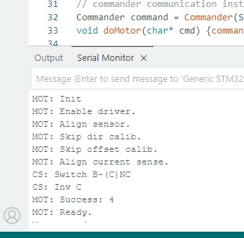
I have success. I started with a new sketch and now have it working.
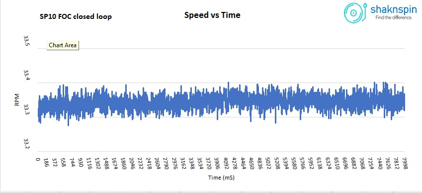
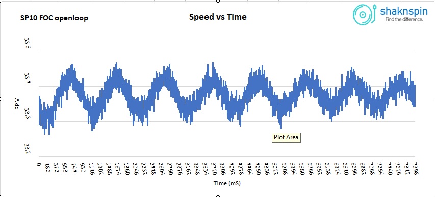
Speed stability is very good, way better than openloop.
One question hopefully someone can answer.
When I alter variables via the commander like KV (MK) and P (MVP) to get the speed to 33.33RPM. Enter these values into the sketch and reload into the STM32 speed is incorrect by 4 - 5%.
Here are 2 speed traces of FOC open and closed loop. I’m using P only no I or D.
Hey, it looks like you still have some oscillations in there that you can maybe tune out with some small adjustments of the velocity PID…
Also for record players the load can be assumed to be very constant, so you can smooth the velocity quite a bit with the LPF.
As to why the parameters lead to small variations in performance between setting them with commander and hard-coding them: I assume it has to do with the parts of the system that can vary, so for example the exact electrical zero value found during calibration, or the temperature of the driver electronics…
I tried adding I = 0.001 but it oscillates significantly, even dropping I = 0.00001 it’s still oscillating slightly. I’ve never tuned a PID before so I’m shooting in the dark.
The whole point of this exercise is to learn coding and FOC. If I’m successful I’ll add sensors. The motor has 3x VRR sensors which are 120° around the stator and accurately aligned to the motor poles. The motor is self commutating with these 3 VRR’s. I could use them as virtual Hall Sensors and a separate Frequency Generator.