Hi!
First post so bare with me ![]()
Building a smaller pan/tilt rig for a 250gr SonyHX90 using a 2 BLDC motor gimbal setup.
3D printed all parts, assembled and connected everything up…

Running SimpleFoc library 2.3.0 on ESP32 with the SimpleFocMini driver, AS5600 via I2C and a cheap smaller china gimbal motor.
Probably attacking this the wrong way. Looked at a few youtube videos. Advise was to start with velocity mode and then angular.
Found a angle example sketch.
Not 100% about my motor spec but looking at a few pages it looks like 12V max 12N14P configuration.
Defined a few pins
#define TILT_ENABLE 18  // Blue
#define TILT_IN1    17  // White
#define TILT_IN2    16  // Grey
#define TILT_IN3    19  // Purple
#define TILT_PP     7   // PolePair from 12N14P
Configured polepair, driver and sensor
// BLDC motor & driver instance
BLDCMotor motor = BLDCMotor(7);
BLDCDriver3PWM driver = BLDCDriver3PWM(TILT_IN1, TILT_IN2, TILT_IN3, TILT_ENABLE);

// encoder instance
MagneticSensorI2C sensor = MagneticSensorI2C(AS5600_I2C);
Readings from my sensor seems fine running a minmal sketch and turning the motor.
velocity PID tuning and filter settings
  // velocity PI controller parameters
  motor.PID_velocity.P = 0.3f; // was 0.2f
  motor.PID_velocity.I = 8; // was 20
  motor.PID_velocity.D = 0;
  // default voltage_power_supply
  motor.voltage_limit = 12;
  // jerk control using voltage voltage ramp
  // default value is 300 volts per sec  ~ 0.3V per millisecond
  motor.PID_velocity.output_ramp = 1000;

  // velocity low pass filtering time constant
motor.LPF_velocity.Tf = 0.001f; // was 0.01f
I cannot get to a smooth rotation using velocity control.
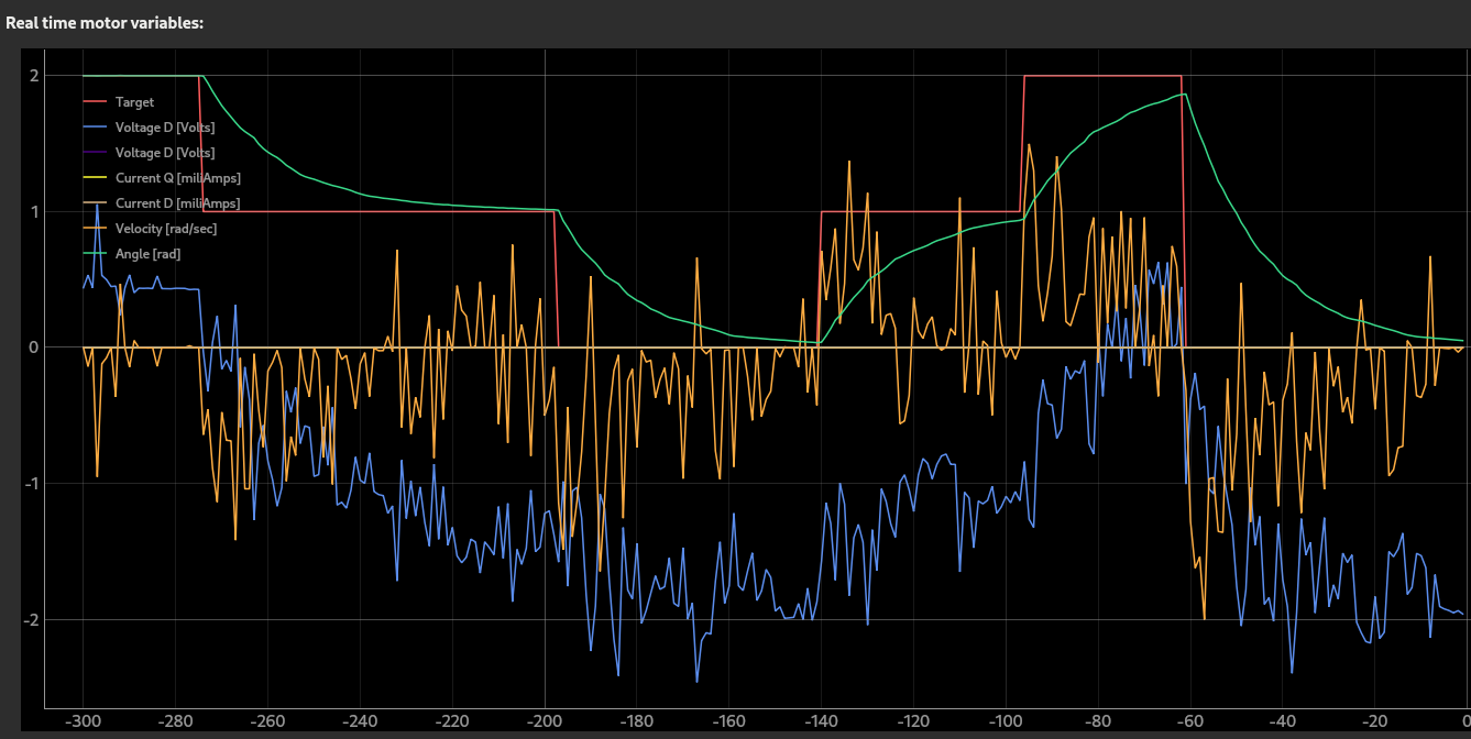
Downloaded SimpleFOCStudio
But it failed to start due to missing QT materials on my Fedora setup so had to start it using
QT_QUICK_CONTROLS_STYLE=Material python simpleFOCStudio.py

Struggle to get the SimpleFOCStudio creating graphs consistently. Most of the time I just get errors via serial
unknown cmd err
unknown cmd err
unknown cmd err
unknown cmd err
unknown cmd err
List devices return the M:motor
Some properties are updated. Like if the driver is enabled or not. But as you can see the legend is not working on the graph. Not really knowledgable in PID control theory or tuning but looks to me that P is too small since it takes time to reach the net set target value.
I have the following in my sketch for the angle part
  // angle P controller
  motor.P_angle.P = 1.0f; // was 20
  motor.P_angle.I = 0.0f; // was 20
  //  maximal velocity of the position control
  motor.velocity_limit = 6;
It’s a bit of copy & paste but not sure why the motor.velocity_limit is under the angle section.
Could that also be a contributor to why it takes time to reach either target speed or angle.
Also very jerky movement. And when running angle it make a lot of noise at the fix point.
Looking at my benchsupply current is a 0.2amp max.
I think I need to get a smooth rotation using velocity first if I understand correctly.
I’ve started questioning the polepair setting and maybe even if I connected the phases correctly.
Found the calibration sketches. find … polepair… kv… But they are not working “as expected”.
MOT: Monitor enabled!
MOT: Init
MOT: Enable driver.
MOT: Align sensor.
MOT: sensor_direction==CCW
MOT: PP check: fail - estimated pp: 12.34
MOT: Zero elec. angle: 4.35
MOT: No current sense.
MOT: Ready.
Motor ready.
Set the target voltage : - commnad T
Calculate the motor KV : - command K
2.000   <- T2
0.39     <-K
KV value seems like a non-typical-kv value
And… Motor initialization fails with PP check: fail - estimated pp: 12.34
A lot of questions. But maybe starting focusing on one of them.
I guess nailing the motor spec, winding, polepair, KV, getting it connected correctly is a first…