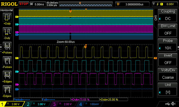
Apologies, I was using a non DAC pin to plot dc_a ![]() There’s only 2 DAC pins available, when I plot dc_a on one of them, it looks just like dc_b and dc_c (shifted)
There’s only 2 DAC pins available, when I plot dc_a on one of them, it looks just like dc_b and dc_c (shifted)
A phase was my mistake, it looks like the others, I’ll do the test you suggested next
how are these plots being generated?
in BLDCDriver3PWM::setPwm:
analogWrite(PA4, dc_a * 4095);
analogWrite(PA5, dc_b * 4095);
Also, if you know any BLDC motor with Hall effect sensors that works with SimpleFOC, please share, I would like to get one for sanity check. Thank you!
I changed it to:
driver.setPwm(0.25 * driver.voltage_limit, 0.5 * driver.voltage_limit, 0.75 * driver.voltage_limit);
So I can get 25, 50, and 75% instead, it looks correct to me:
Ok, this last trace clearly shows the PWM is working as expected… so back to square one, as they say…
I would assume right now it has to be related to the sensors somehow, but must admit I’m a bit confused what the issue is…


