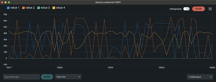
First - thanks so much for the efforrts put into this! My project woldn’t be possible without it and it’s been a lot of fun learning about FOC control.
Project - 3 axis reaction wheel similar to the famous “Cubli” My thought was to use torque control as that is the desired control parameter but I am not sure if I understand how SimpleFOC torque control was intended to be used.
ESP 32
7PP 11.3 ohm 200 KV motor
AS5048 magnetic encoder
SimpleFOC shield V2
Current sensing
Closed loop torque control
I am pretty sure I have everthing running correctly. Evertying initializes correclty.
Just for testing I am running the motor using commander. When in torque control and I command a torque, M0.01 for example, the current ramps up slowly to the max (holding motor stationary). I expected the commanded torque to remain constant. While playing around with the pid’s I noticed I got the expected behavior by adjusting the limit. “motor.PID_current_d.limit”
With closed loop torque control, does the torque ramp when the commanded torque is non zero? Or is it intended to maintain the commanded torque?
If my goal is to use torque control (or current control) would it be acceptable to command changes to motor.PID_current_d.limit?
Code:
#include <SimpleFOC.h>
#define HSPI_MISO 19
#define HSPI_MOSI 23
#define HSPI_SCLK 18
#define HSPI_SS 5
unsigned long timestart = 0;
unsigned long timemiddle = 0;
bool inside = 0;
int speed1 = 500;
int speed2 = 500;
int maxspeed = 0;
// this is the full setup program. Use this one as the master KH 1/24/23
// BLDC motor & driver instance
// BLDCMotor(int pp, (optional R, KV)) KV 50-70% higher than actual
BLDCMotor motor = BLDCMotor(7,11.3,200); // large motor 11,7.1,80
BLDCDriver3PWM driver = BLDCDriver3PWM(27, 26, 25, 33);
// // magnetic sensor instance - I2C (NOT USED)
// MagneticSensorI2C sensor = MagneticSensorI2C(AS5600_I2C);
// Magnetic sensor instance - SPI
// MagneticSensorSPI(int cs, float _cpr, int _angle_register)
// cs - SPI chip select pin on ESP32
// bit_resolution - magnetic sensor resolution
// angle_register - (optional) angle read register - default 0x3FFF
// MagneticSensorSPI sensor = MagneticSensorSPI(10, 14, 0x3FFF);
MagneticSensorSPI sensor = MagneticSensorSPI(AS5048_SPI, HSPI_SS);
// for esp 32, it has 2 spi interfaces VSPI (default) and HPSI as the second one
// to enable it instatiate the object
SPIClass SPI_2(HSPI);
// inline current sensor instance
InlineCurrentSense current_sense = InlineCurrentSense(0.01, 50.0, 39, 36);
// current set point variable
float target_current = 0;
// instantiate the commander
Commander command = Commander(Serial);
// void onMotion(char* cmd) { command.motion(&motor, cmd); }
void onMotor(char* cmd){ command.motor(&motor,cmd); }
unsigned long timestamp = micros();
void setup() {
// Sensor Init
// Link motor to sensor
// Driver Init
// Link the current sensor to driver
// Link driver to motor
// Motor Init
// Current Sense Init
// Link current sense to motor
// // invert phase b gain
// current_sense.gain_b *=-1;
// // skip alignment
// current_sense.skip_align = true;
// FOC START
Serial.begin(115200);
// initialise magnetic sensor hardware
// start the newly defined spi communication
SPI_2.begin(HSPI_SCLK, HSPI_MISO, HSPI_MOSI, HSPI_SS); //SCLK, MISO, MOSI, SS
// initialise magnetic sensor hardware
sensor.init(&SPI_2);
Serial.println(“Sensor ready”);
// link the motor to the sensor
motor.linkSensor(&sensor);
// driver config
// power supply voltage [V]
driver.voltage_power_supply = 12;
driver.init();
// link current sense and driver
current_sense.linkDriver(&driver);// link driver
// link the driver to the motor
motor.linkDriver(&driver);
// aligning voltage
motor.voltage_sensor_align = 5;
// // choose FOC modulation
// // FOCModulationType::SinePWM; (default)
// // FOCModulationType::SpaceVectorPWM;
// // FOCModulationType::Trapezoid_120;
// // FOCModulationType::Trapezoid_150;
// motor.foc_modulation = FOCModulationType::SpaceVectorPWM;
// // aligning voltage [V]
// motor.voltage_sensor_align = 3; // default 3V
// set torque mode:
// set torque mode to be used
// TorqueControlType::voltage ( default )
// TorqueControlType::dc_current
// TorqueControlType::foc_current
motor.torque_controller = TorqueControlType::foc_current;
// set motion control loop to be used
// MotionControlType::torque - torque control
// MotionControlType::velocity - velocity motion control
// MotionControlType::angle - position/angle motion control
// MotionControlType::velocity_openloop - velocity open-loop control
// MotionControlType::angle_openloop - position open-loop control
motor.controller = MotionControlType::torque;
// motor.controller = MotionControlType::velocity;
// controller configuration based on the control type
// velocity PID controller parameters
// default P=0.5 I = 10 D = 0
motor.PID_velocity.P = 0.2;
motor.PID_velocity.I = 3;
motor.PID_velocity.D = 0;
// jerk control using voltage voltage ramp
// default value is 300 volts per sec ~ 0.3V per millisecond
motor.PID_velocity.output_ramp = 1000;
// velocity low pass filtering
// default 5ms - try different values to see what is the best.
// the lower the less filtered
motor.LPF_velocity.Tf = 0.01;
// setting the limits
// either voltage
motor.voltage_limit = driver.voltage_power_supply; // Volts - default driver.voltage_limit
// of current
motor.current_limit = 2; // Amps - default 0.2Amps
// foc current control parameters (Arduino UNO/Mega)
// Q axis
// PID parameters - default
motor.PID_current_q.P = 5; // 3 - Arduino UNO/MEGA
motor.PID_current_q.I = 1000; // 300 - Arduino UNO/MEGA
motor.PID_current_q.D = 0;
motor.PID_current_q.limit = 30;
motor.PID_current_q.output_ramp = 1e6; // 1000 - Arduino UNO/MEGA
// Low pass filtering - default
motor.LPF_current_q.Tf= 0.01; // 0.01 - Arduino UNO/MEGA
// D axis
// PID parameters - default
motor.PID_current_d.P = 5; // 3 - Arduino UNO/MEGA
motor.PID_current_d.I = 1000; // 300 - Arduino UNO/MEGA
motor.PID_current_d.D = 0;
motor.PID_current_d.limit = 30;
motor.PID_current_d.output_ramp = 1e6; // 1000 - Arduino UNO/MEGA
// Low pass filtering - default
motor.LPF_current_d.Tf= 0.01; // 0.01 - Arduino UNO/MEGA
// comment out if not needed
motor.useMonitoring(Serial);
// initialize motor
motor.init();
// current sense init hardware
current_sense.init();
// link the current sense to the motor
motor.linkCurrentSense(¤t_sense);
// invert phase b gain
current_sense.gain_b *=-1;
// // skip alignment
current_sense.skip_align = true;
// align sensor and start FOC
motor.initFOC();
// init current sense
if (motor.initFOC()) Serial.println(“FOC init success!”);
else{
Serial.println(“FOC init failed!”);
return;
}
// add target command T
// command.add(‘M’, onMotion, “motion control”);
command.add(‘M’, onMotor,“my motor motion”);
Serial.println(F(“Motor ready.”));
Serial.println(F(“Set the target current using serial terminal:”));
_delay(1000);
}
void loop() {
// main FOC algorithm function
motor.loopFOC();
motor.move();
// user communication
command.run();
}
