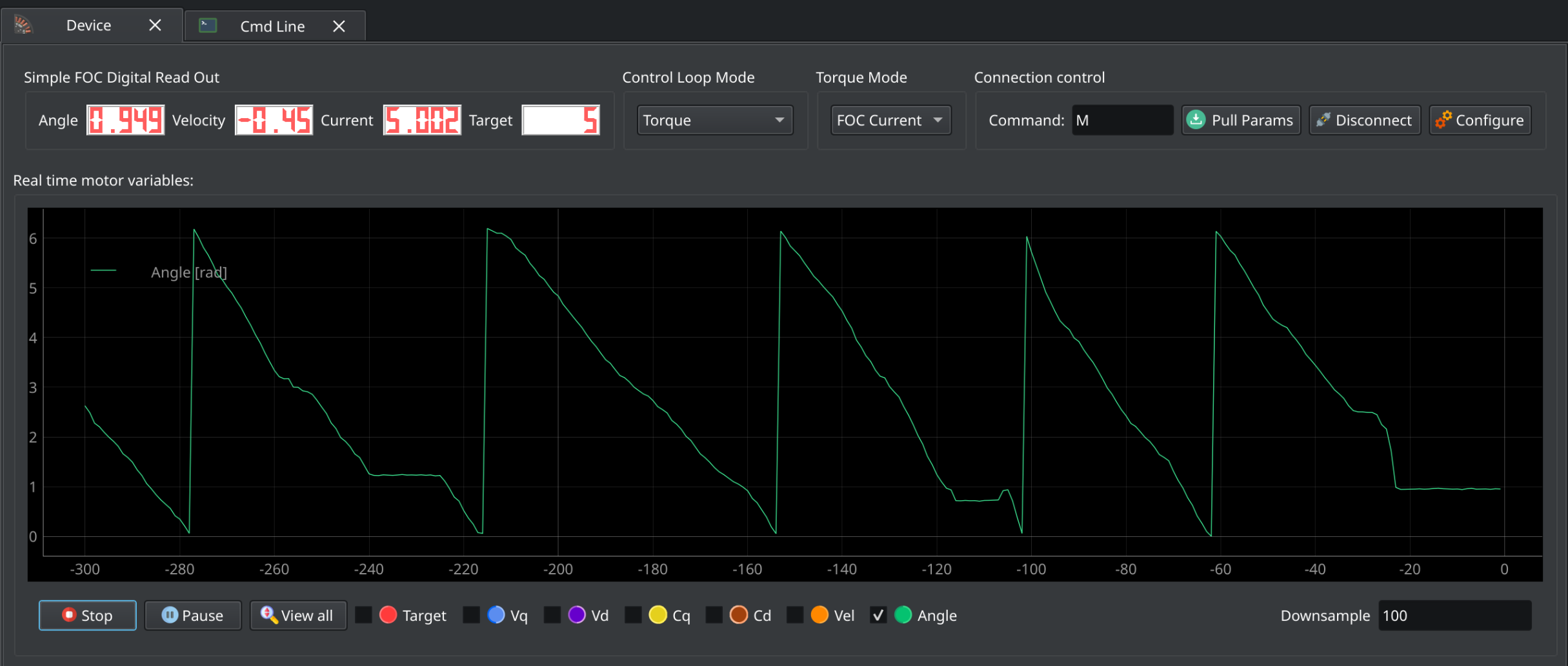
I’m a bit stumped here. I’m trying to get torque control working and tuned but the only thing I manage to get is a locked motor. It target the current correctly but I get no motion no matter how much currently I put through this thing.
I’m using an esp32 s3 with low side sensing and a custom encoder. I’ve verified the encoder actually reads the correct angle. I’ve tried clockwise and counter clockwise rotation.
I’ve also tuned the current q and d PID loops to see if that would help. It did not.
Voltage control, DC current control, and FOC current control all give the same results, the correct target current with a locked rotor.
Attached is my cleaned code. I’ve removed quite a bit of custom stuff that I think is irrelevant.
#include <Arduino.h>
#include <SimpleFOC.h>
#include “HardwareSerial.h”
#include “esp32-hal.h”
// Irrelevant includes //
// Pin definitions for other libs //
// Monitoring setup
#define _MON_TARGET 0b1000000 // monitor target value
#define _MON_VOLT_Q 0b0100000 // monitor voltage q value
#define _MON_VOLT_D 0b0010000 // monitor voltage d value
#define _MON_CURR_Q 0b0001000 // monitor current q value - if measured
#define _MON_CURR_D 0b0000100 // monitor current d value - if measured
#define _MON_VEL 0b0000010 // monitor velocity value
#define _MON_ANGLE 0b0000001 // monitor angle value
// — DRV8323S Library Instance — //
// A quick delay function
void short_yield_to_idle(void) {
TaskHandle_t self = xTaskGetCurrentTaskHandle();
UBaseType_t orig_pri = uxTaskPriorityGet(self);
if (orig_pri > tskIDLE_PRIORITY) {
// lower priority by 1 so IDLE (priority tskIDLE_PRIORITY) becomes runnable
vTaskPrioritySet(self, orig_pri - 1);
taskYIELD(); // immediate context switch
vTaskPrioritySet(self, orig_pri); // restore
} else {
// already idle-priority: yield once
taskYIELD();
}
}
// BLDC motor & driver instance
// BLDCMotor motor = BLDCMotor(pole pair number);
BLDCMotor motor = BLDCMotor(7, 0.027, 2800);
// BLDCDriver6PWM driver setup
BLDCDriver6PWM driver = BLDCDriver6PWM(1, 2, 3, 4, 5, 6);
// instantiate the commander
Commander command = Commander(Serial); // Use Serial for commander
void doMotor(char* cmd) { command.motor(&motor, cmd); }
// LowsideCurrentSense(shunt_resistance, gain, adc_a, adc_b, adc_c)
LowsideCurrentSense current_sense = LowsideCurrentSense(0.001, -20, 10, 9, 8);
void setup() {
// Set up the ADCs for low side current sensing
analogSetAttenuation(ADC_11db); // Sets 0-3.3V range for all ADC pins
Serial.begin(115200); // Use Serial for initialization
// Configure and enable DRV8323S enable pin at the very beginning
while(!Serial) {
delay(10); // Wait for USB CDC connection
}
SimpleFOCDebug::enable(&Serial);
// Initialize SPI Bus
// Initialize the DRV8323S (use_csa = true for current sensing)
// Actually keeping this part since it deals with my CSA
// Configure custom OCP settings if needed (optional)
OcpControl ocp = drv8323.getOcpControl();
ocp.vds_lvl = VdsLvl::V0_26; // 0.26V threshold
ocp.ocp_mode = OcpMode::ReportOnly;
drv8323.setOcpControl(ocp);
// Configure custom CSA settings if needed (optional)
CsaControl csa = drv8323.getCsaControl();
csa.csa_fet = false;
csa.vref_div = false;
csa.ls_ref = false;
csa.csa_gain = CsaGain::G40;
csa.dis_sen = false;
csa.csa_cal_a = false;
csa.csa_cal_b = false;
csa.csa_cal_c = false;
csa.sen_lvl = SenLvl::V0_25;
drv8323.setCsaControl(csa);
// Read the fault registers just in case
// --- Driver --- //
// power supply voltage [V]
driver.voltage_power_supply = 7.5;
// Set the pwm to 20khz
driver.pwm_frequency = 20000;
// Initialize the driver.
driver.init();
// --- Custom encoder setup --- //
// Initialize sensor
sensor.init();
// Option 1: Run calibration (spin motor by hand for 10 seconds)
sensor.calibrate(10000);
// --- Control Type --- //
// Set up velocity control
motor.controller = MotionControlType::torque;
// Use FOC current control
motor.foc_modulation = FOCModulationType::SpaceVectorPWM;
// --- Motor Values --- //
// Cap the current at a maximum level
motor.current_limit = 12; // amps
// Cap the driver voltage
motor.voltage_limit = 0.4; // about 14 amps
// link the motor and the driver
motor.linkDriver(&driver);
// Link the positional sensor
motor.linkSensor(&sensor);
// --- Current Sensing --- //
// Link the current sensing and initialize it
current_sense.linkDriver(&driver);
// init current sense
if (current_sense.init())
Serial.println("Current sense init success!");
else{
Serial.println("Current sense init failed!");
return;
}
// link the motor and the current sensor
motor.linkCurrentSense(¤t_sense);
// --- PID Values --- //
// velocity low pass filtering time constant
motor.LPF_velocity.Tf = 0.02;
// current q loop PID
motor.PID_current_q.P = 0.2;
motor.PID_current_q.I = 0.5;
motor.PID_current_q.D = 0.0;
motor.PID_current_q.output_ramp = 0.0;
motor.PID_current_q.limit = 0.4;
// Low pass filtering time constant
motor.LPF_current_q.Tf = 0.1;
// current d loop PID
motor.PID_current_d.P = 0.6;
motor.PID_current_d.I = 0.8;
motor.PID_current_d.D = 0.0;
motor.PID_current_d.output_ramp = 0.0;
motor.PID_current_d.limit = 0.4;
// Low pass filtering time constant
motor.LPF_current_d.Tf = 0.1;
// initialise motor
motor.init();
// skip alignment procedure
// current_sense.skip_align = true;
// invert phase gains
current_sense.gain_a *= -1;
current_sense.gain_b *= -1;
current_sense.gain_c *= -1;
// Set the motor to check the angle every 5 foc calls
motor.motion_downsample = 5;
// Set the expected direction for the sensor
motor.sensor_direction = Direction::CCW; // Direction::CW;
// Initialize FOC
motor.initFOC();
// set the inital target value
motor.target = 0;
// define the motor id
command.add('M', doMotor, "motor");
motor.monitor_variables = _MON_TARGET | _MON_VOLT_Q | _MON_VOLT_D | _MON_CURR_Q | _MON_CURR_D | _MON_VEL | _MON_ANGLE;
motor.monitor_downsample = 10; // default 10
// use monitoring with serial
motor.useMonitoring(Serial);
}
void loop() {
// main FOC algorithm function, the higher the execution frequency, the better, don't put delays in the loop
motor.loopFOC();
// this function can be run at much lower frequency than loopFOC()
motor.move();
// significantly slowing the execution down
motor.monitor();
// user communication
command.run();
// Allow the watchdog time to catch up
short_yield_to_idle();
}
Open loop velocity and position work just fine. Cogging is noticeable there but it’s not bad.