Hi
Finally ready to test the design.
Would you support a kickstarter ?
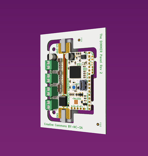
Processor: 120Mhz ATSAME51
Dimensions: 37mm wide x 58mm high
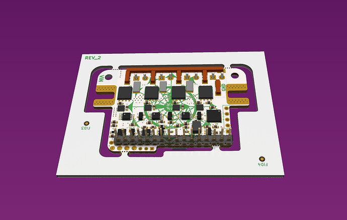
The wire lugs has a 85amp rating, but to integrate the board into a CNC routed heatsink/enclosure wires can be soldered on top side.
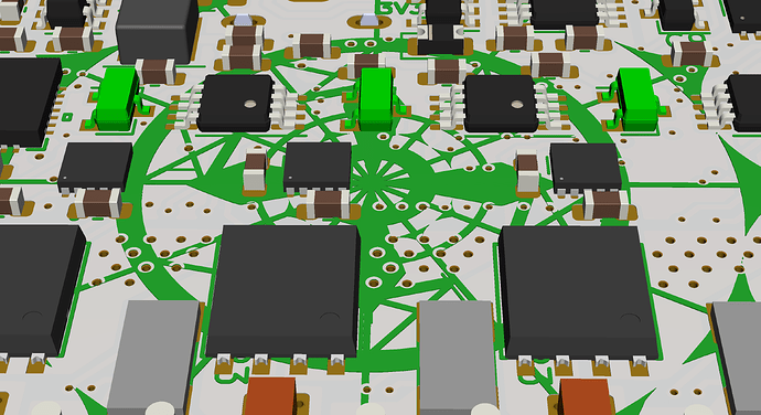
Half bridges (IAUC60N04S6L030H) 60 amp rated, driven by 10v Switching mode power supply. VIN 12/24V.
500mA continuous 5V LDO / 500mA peak 3.6V LDO MIC5219
Onboard TMC2209 (Can be used for steering when used for robotics)
As mentioned in another thread, there are 3 analog hall sensors w. filtered output. These 3 hall sensors is aligned to NEMA23 center of rotation and will hopefully give a very high resolution control loop for running some beefy steppers.
You can read more about the project here. Will do a test run and then hopefully crowd fund the concept. As you can read on the hackaday page, the board is designed with LED dimming in mind. The idea is to do a open source grow-light for educational purposes. Yes grow-lights for schools. My goal is to experiment on how we can utilise the excess heat from a highly efficient LED lamp.


