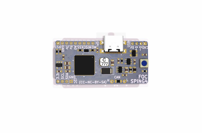
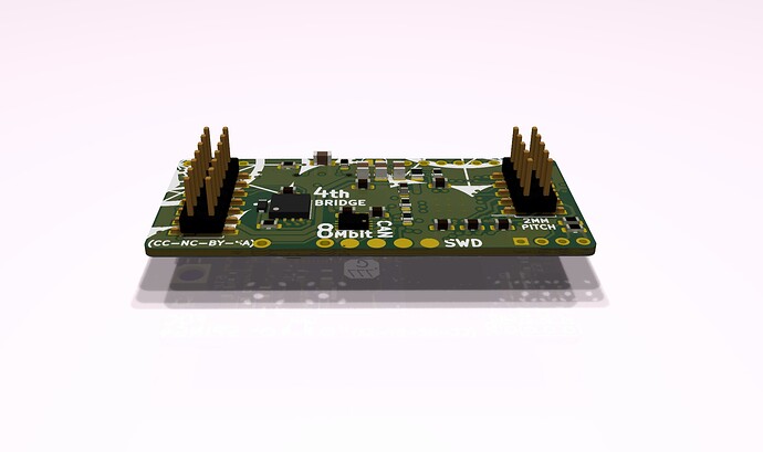
For the record, this iteration is a continuation from another thread. It seams I have taken some large de-tour in order to reach this physical manifestation. Anyhow, I believe I have sketched up something useful, although there are some uncertainties, like will the buck-converter to LDO step-down work as expected.
I have chosen to add a external 3.3v LDO for external use and for the ANALOG domain. This means the internal LDO will supply the IO domain and all other MCU stuff, clock etc. The reason for doing this, is to not over-burden the internal LDO, which has a 120mA limit. Furthermore I have chosen to put a 5V LDO in between the buck and the internal LDO in order to avoid too much heat. Doing this we can maybe turn up the buck voltage to eg. 14v and still be in the zone.
I still have some doubt about the clock, since STM uses a 24MHZ crystal in their reference design. Is this the same for the B-G431B-ESC1? The 32.768 clock pins is right next to the ones STM use, so choosing that approach is not an issue…
EDIT: If HALL sensors are used for motion-sensor purposes, then the SPI pins on the dual-row headers should be used and set up w. pull-ups etc. on the daughter-board/power-stage. The CAL_MT6835 pin is placed on PC5 which has ADC2_IN11 (slow analog input). With this pin, the motor temperature can be monitored, if using HALLs that is. Power-Stage thermistor is broken out on a separate pin w. ADC2_IN5 (PC4 - fast analog input).

