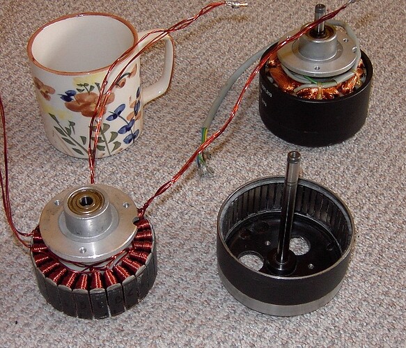
Ok, so I am desiging, still, a very low noise fan. Things are looking good but the motor driver needs work. The motor is significantly coggy and I can’t get a lower cogging motor.
Fundamentally I’ve been able to ascertain that the cogging torque is mostly a sine wave at 44 cycles per revolution of the motor. It’s an 11 pole pair motor. I tried to count the detents the motor exhibits by hand, I repeatedly counted 43 but assume I made a mistake and it’s 44.
As a quick refresher, the cogging torque is caused by the magnets being attracted to the iron core of the poles. It’s a torque ripple imposed on the rotational torque which I think is probably not changing with rpm and power level, although the saturation of the core might have an impact, I suspect, that would imply poor efficiency or high power level operation.
What I need is to impose a sine wave of the same frequency onto the voltage waveform, preferrably adjustable inthe main loop, to cause a torque ripple that cancels out most of the cogging torque. Then I’ll connect a potentiometers I think (if there is a pin for that handy on the adc) and adjust the amplitude during operation till the noise is iminimal by reading the adc and using that as an adjustment value. Then I can at least do my testing.
My priority is to test the fan to measure the noise the blades are making, but right now all the motor drivers I have make so much noise they drown out the noise from the blades and I cannot get a useful reading.
It can require manual intervention or whatever, I gotta start somewhere.
I am not so good with arduino although I know some I have difficulty.
So my question is can anyone think of a good strategy to atttack this? If I take the position in radians, multiply by 44, make it a global variable that can be accessed, and insert a function in between function that gets the voltage for the waveform (before it gets converted to a PWM value) and imposes that little voltage ripple the way I want, by looking up the sine of the position in radians multiplied by 44, adds it to the previous voltage , then feeds it back where the voltage is supposed to go.
So I jack in in the right point and impose the ripple I want, with the right phase, which should mostly cancel the cogging ripple. Makes sense? The ideal voltage amplitude will probably not stay constant across rpm, but I can do something that works best at the goal rpm (300 rpm) and will still work a bit at other rpms.
Enough I can get a measurement and learn more, basically.
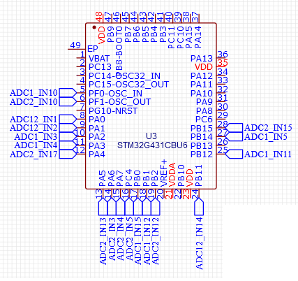
I’m trying to use the QVADRANS but I only have 1 left so if I fry it I may need to pull out my B-g431-ESC1 boards.

