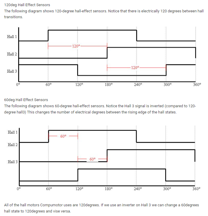
Just having another look at the hall sensors on my motor in detail, and I notice that instead of them all having equal 50% duty (180deg on 180 deg off) I have only 1 of the 3 hall’s correct, the others are 33% duty (120deg on)
I think my hall’s are 60deg apart. Does that sound right, or is there something wrong … I understand zeros and 7’s as a hall code are legal for 60deg …
That is weird, i’d expect them to all be on 50% of time. Sometimes, with inadequate pullups you see them flipping from high to low when they should be high, but i don’t think you are Singh that
Zero and 7 is illegal on normal hall arrangement but i guess there might be variations that use it
The magnets are separated by 120 degrees (electrical).
@Owen_Williams Yep, I think my halls are only 60deg apart. However they should still be 50% duty as per @Candas1 diagram. (0 & 7 codes are legal for 60deg)
I think on the original controller for this motor, the halls were supplied by 12v but the OC outputs are pulled up to CPU 3v3. I only have a 5v supply so maybe the halls are not working correctly at that lower voltage.
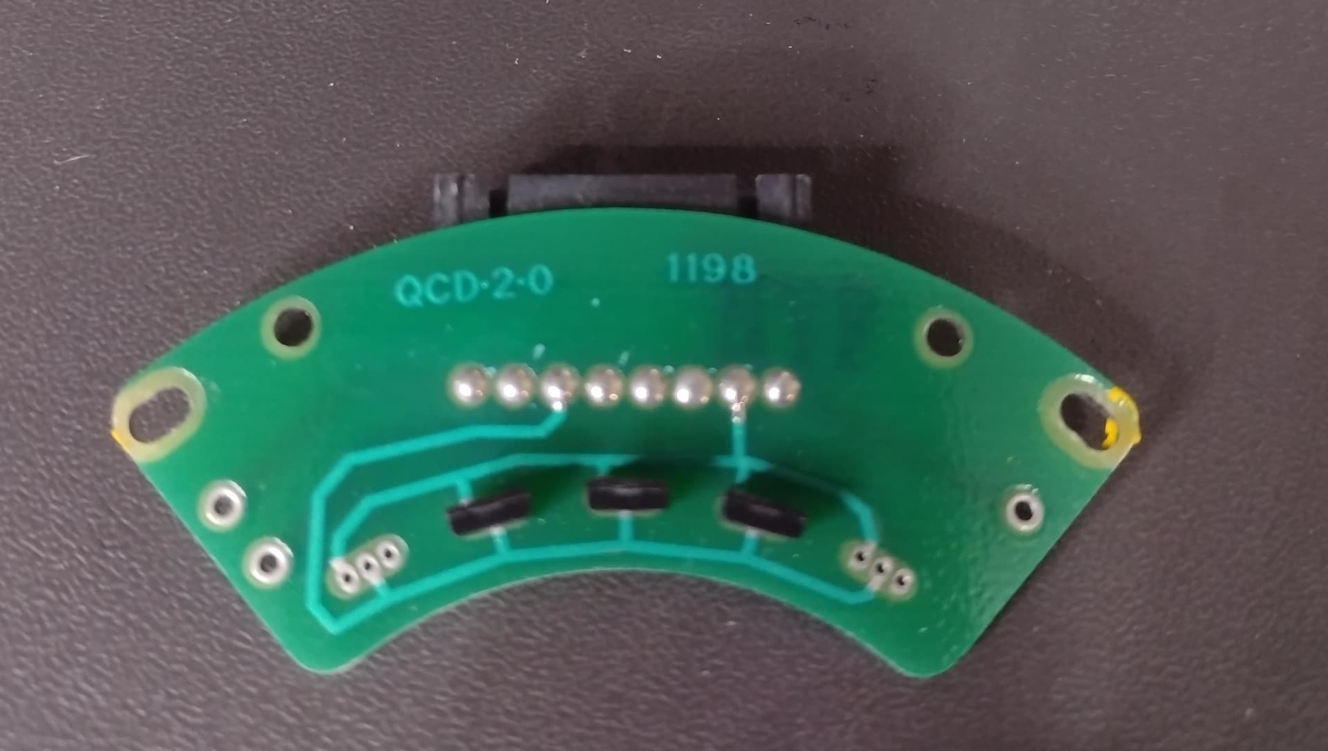
I might pull one to bits and have a look what halls it uses …