Hello all
A few weeks ago I made an adapter board to connect the SimpleFOCShield to the STM32F4 Black Pill and it works great.
I’ve made a lot of projects in the past with Arduino, Raspberry Pi, ODrive, sensors, other modules, … but I never made a custom PCB for these projects even though I wanted to make one for a long time. Now I was thinking why don’t I make a PCB that combines the STM32F4 Black Pill and the SimpleFOCShield on one PCB because I like the MCU a lot and the SimpleFOCShield schematic is easy and I already have an L6234 chip. Also, I’m studying electromechanical engineering so maybe I can use this PCB designing skill in the future, I have some electrics knowledge.
Now the task at hand is reverse engineering the MCU with the given schematic and visual inspection of the board because the schematic is not complete.
I’m making this board for fun and practice, in the future I want to design a better board.
Links to the MCU:
Questions/thoughts:
-
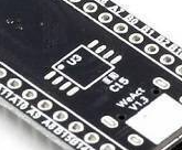
Flash
There is a place on the back of the board for a flash chip I will leave this out of my design, I don’t think there is anything I need to worry about when removing this from the schematic.
-
Diode
there is an S4 diode on the board that is not in the schematic, what does this do and where is it placed? It is connected to the top pin of the USB connector.
-
C13 LED and KEY
I will also remove the LED on pin C13 and the KEY button, this is just an onboard input button.
-
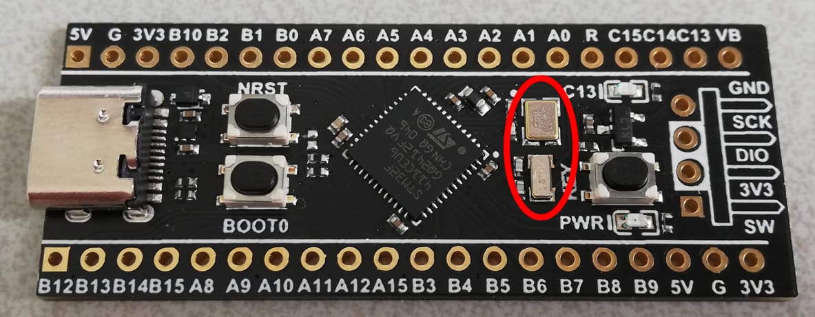
Crystals
There are two crystals, the top one is 25 MHz and the bottom one is 32.768kHz according to this website: Black Pill clock sources, but I can’t seem to find the lettering on the chip on the internet which is X2E18A, what footprint is this? Also which one is the LSE and HSE one on the schematic?
-
Voltage regulator
I wanted to use 2 AMS1117’s, one for 3.3V and one for 5V but the board has a 4B2K regulator, is it better to keep this one, why?
-
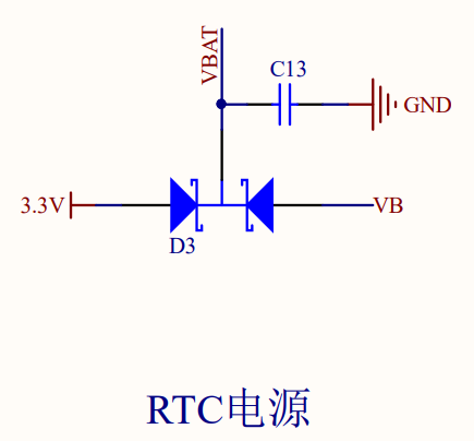
KL3 double diode
There is a KL3 double diode on the board, what does this do and what do VBAT and VB stand for? Can I remove this part of the schematic? Runger already gave me an answer but I want to add this to make this post complete in case someone wants to add to this.
-
Unknown resistor and capacitor values
How should I go about finding the resistor and capacitor values that are not given in the schematic? Desolder them and measure? -
Missing component
I think there is a missing component next to the reset button, any reason why?
-
USB interface
Does the STM32F4 have native USB support because it does not seem that there is a USB controller on the board or is this done with a certain firmware?


My schematic: SimpleFOCSTM32
Any other tips and ideas are of course welcome!
Thanks for your time and help.
Carelsbergh Stijn
