Im very begginer and just want to know how hard would it be or if someone can help me with basic code to spin a hub motor (motorcycle) 72v with a custom board with a stm32f103cb76.
i have present the pins going to and from mcu and useful components like:
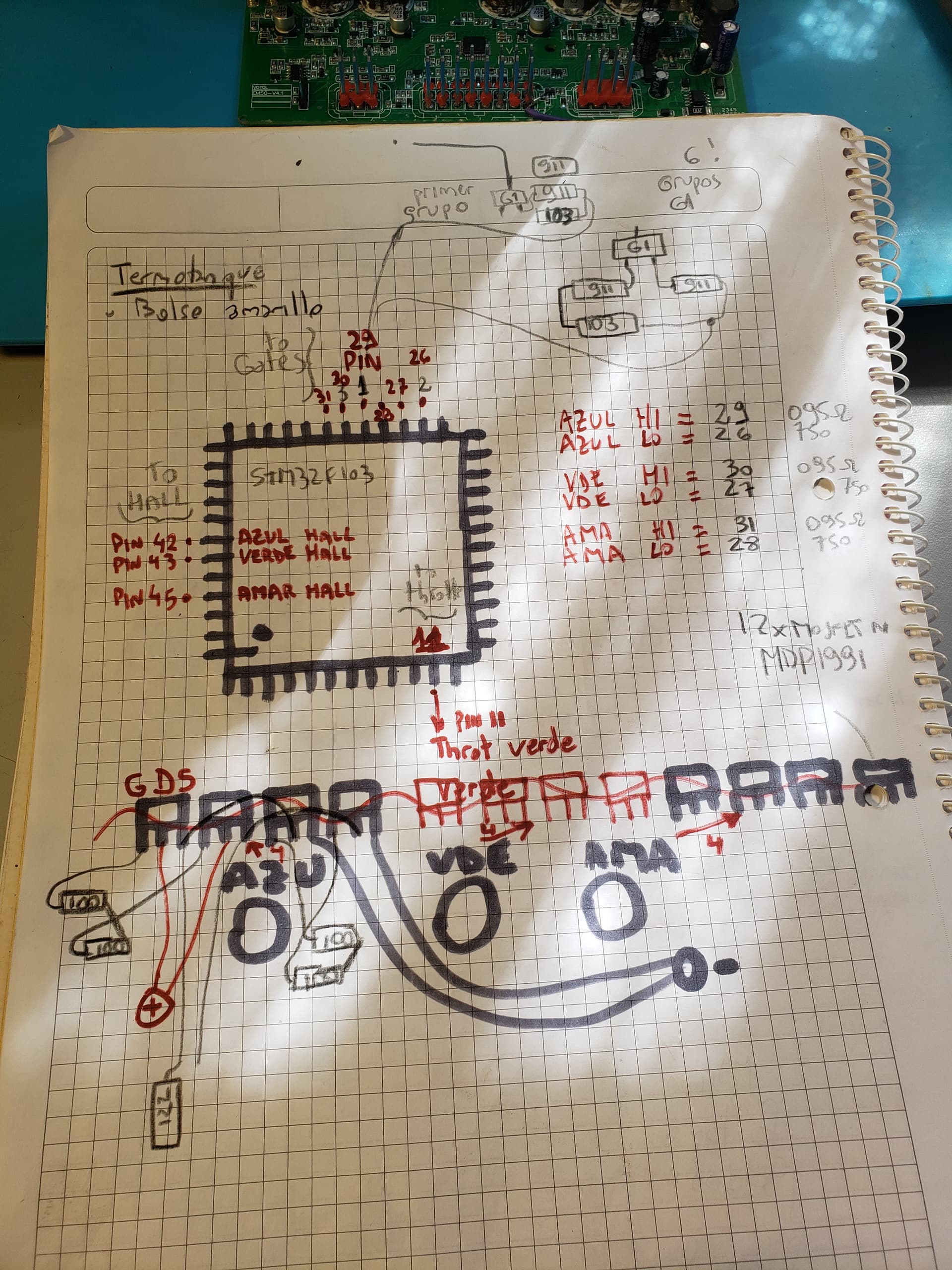
a) throtle signal PIN11
b) hall sensor signal for 3 phases blue green yellow PINS 42 43 AND 45
c) gate drivers 6 signals 3 hi and 3 low side. HI are 29 30 and 31 … LOW are 26 27 and 28
here is a picture of hatdware with 12 mosfets (2 in partallel for each fase and side)
Also note that gate drivers are discrete components … res caps and y2 g1 transistors…
stock firm not available!!
Custom i meant not bluepill or experimental board… not using stock firmware because reflashed with different version and sadly bricked. vendor does not give me Firmware because buyed in alliexpress not in vendor site. If you could help me with proper bin to upload with stlink v2 for example it would be great!
Then you probably need to look for an alternative firmware.
Don’t expect that you will easily get same features as the original firmare with SimpleFOC.
What do you mean by bricked ? I don’t think you can brick an stm32, unless you disable programming pins, which you can still recover.
And I don’t see how you would flash SimpleFOC on it if it’s bricked ?
I don’t think SimpleFOC is the right solution for you if you cannot code.
ok bricked i meant i cant flash any firmware to make it work loke before… it says co.munication abnormal with it own software (windows)
… since it has all mosfets and caps et in good condition… what else would you do? it is now a heavy paper weight… i cant afford a new one and cant wait 120 days to arrive … i prefer learning more and ñartly recover it… what alternative firmware could i try? what would you do?
You have to search forums for bin files, maybe someone had the chip not locked in the factory and saved the firmware. Maybe someone coded a new firmware already. Have you checked endless sphere forum ?
You didn’t come here to learn, you came to ask us to code it for you.
i ve flashed a blink code with cubeide so the mcu is working " in circuit"… not in reset state or damaged… bin files i have the one supposed to be the stock one but after flashed wirh stlink v2 utility refuses to connect… maybe not doing well or something missing… came here for startup help with of my detected pins and motor parameters are enough to make it spin… maybe with a standar code i can achieve this… do not want someone to program me anything just the bare beggining help
Honestly, for a scooter or e-bike it would not be at all safe to use with a self made hacked up firmware… you have to consider your own safety and the other persons on the roads.
If you can find the bin file or elf file for an original firmware we can maybe help you to flash it…
If I understand correctly, if you flashed and stlink refuses to connect, then you bricked the MCU. Even if you get the original firmware you will not be able to re-flash.
There are ways to recover however with an MCU soldered on the mystery board recovering the MCU means you need to lead out all programming pins, put it in DFU mode and then clean the MCU to recover the programming pins (probably re-mapped to who knows what). I don’t even know if it’s possible if the reset and boot pins are soldered to other functions, you may have an unrecoverable problem (unless you desolder the MCU, reprogram it and solder it back, possible but not within your level of skills it seems).
This seems to be way beyond your abilities. Also, the board has braking and what not, I would not touch this without original code, no f-kng way.
Please don’t hurt yourself with this mystery board. Get a real one. Your life isn’t worth hundred bucks.
He could connect under reset but if he has already resistors or other components connected to reset and boot, he is cooked. I don’t se a reset button on the photo which means they used that pin for something, or may be it’s exposed but where? On the 48 lqfp it’s pin #7, not mapped to anything else, it’s possible it’s exposed and he can connect under reset for dfu.
thanks to all, yes I have desoldered the chip and soldered the one from a blue pill board since it is compatible, if you wonder the original is an APM32 FEPSCBT6 instead of stm32f103 … but same behaviour… then programmed with stlink v2 stock firmware back (attached at end) that seems to be the original for my controller, taken from endless sphere,… but again not working… maybe i do not flash right, can you help? soldered back to the controller no problem I have nice microscope and flux… still refuses to connect …“communication abnormal” … talking about security of course!!! im using the motorcycle with my stock controller and this is just for research and learn… maybe i will buy another controller to have more customizable features like regen and flux weakening… that is why i bought this em50s from votol… ye sbut not only 100usd but the time it takes to reach here,
if you can help or check if my way of flashing the firmware is correct I will thanks a lot!!!
placed pins on the board for gnd, swclk and swdio , 3.3v
connected stlink v2
opened STM32 ST-LINK Utility
Target erase chip and blank chek ok
Program and verify of BIN
ok
since no errors after reset and upload, though it would be perfectly flashed…
Also to clarify the problem not connecting is against the Votol app not with the stlink utility so the video did not help…
So you may be able to run SimpleFOC on this board - first question is how much flash your F103 has. You should have 128kB flash or more, or else there will be additional problems getting the code to fit onto the MCU.
Once you have a MCU with enough flash memory, you can flash and run a “blinky” sketch if you have a user-controllable LED… if not, you can “blink” a serial TX pin or use Serial comms, anything to test the MCU is alive. Normally to flash a program you will need the SWDIO, SWDCLK and nRESET lines, or you can also use BOOT0, nRESET and RX/TX for Serial flashing.
You can ignore the Votol utility for now. It will not work again until you flash an original firmware back to the chip.
Once you have verified that you can load and run a basic sketch, it’s time to identify all your pins. For each MCU pin, try and figure out what it does. You can use a multi-meter in beep mode to map connections on the PCB. To get things working you’ll need to figure out which are your low and high side gate signals, and which pins are used for sensors (Hall sensors?)
Once you know the pins, you can plug them into one of our example sketches and give SimpleFOC a try…
well that is what i did … like i ve said before, i tested with a blinking pin (no led, yes a rx pin) and mcu works perfectly fine… compiled with cubeid (not with my prefered arduino ide… because internal hsi is needed (board has no crystal) and do not know how to set it up in arduino ide.
then uploaded with stlink utility in windows…
regarding pins also as i ve said i have
throthe signal
hal a , hal b , hal c
pha low, phb low, phc low
and pha hi, phn hi and phc hi
…
of course it would be great to get back to the stock bin attached before… its f103 with 128lb yes.
because i lost alarm regen flux weak …remote key less on off… etc
So… can anyone give raw directions for a simple “spinning motor” code, considering my pins, a basic start point, just with hall sensor and throttle pins:
a) throtle PIN11
b) hall sensor PINS 42 43 AND 45
c) gate HI are 29 30 and 31 … LOW are 26 27 and 28