Hi forum,
I am having a hard time getting any kind of closed loop control (torque, velocity) to work with the STM32-G431B-ESC1 evaluation board.
Just for clarity, I have read these blogs:
Blog 1
Blog 2
Also, I have followed this guide with succes until closed-loop.
The same applies to following these excellent videos:
The application:
STM32-G431B-ESC1 board with this motor.
Power supply is 3A current limited 24V bench supply.
Want to use it to make a belt-driven motor platform for my turntable (for records).
I reckon that I once have followed the above-mentioned videos (and with succes at torque control at low voltages), then started tuning my PID controller for velocity control, and then suddenly, whatever control method, target value, i.e. I’m trying, the motor gets stalled and is drawing ~ 5-800 mA of current.
So I went back to basics and started verifying step for step:
-
The driver.setPwm(2,4,6); method sets different average values of the phase outputs referenced to ground. They are not precise (+/- 1V), but they increase/decrease according to different arguments.
-
Open-loop velocity works fine (little noisy, but I guess this is to expect) for ~40 rad/s target.
At 40 rad/s, the phases look like this:
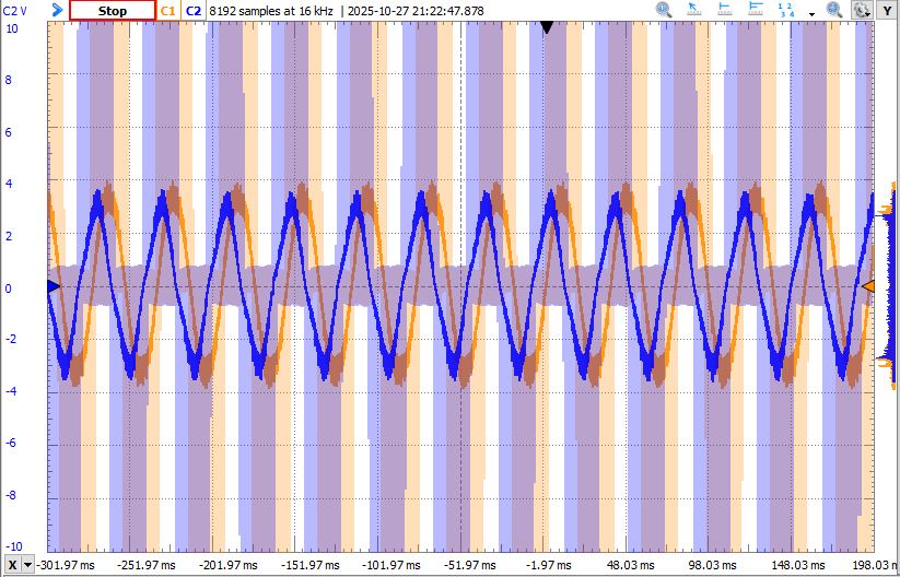
Blue: Phase W - Phase U
Orange: Phase V - Phase U
It is clear that target 6.28 rad/s makes one revolution per second.
Found my “sweetspot” at voltage_limit = 2.0 and voltage_sensor_align = 2.0. Above/below these values, the motor starts misbehaving.
-
I verified hall-sensor. One full 360 degree rotation returns 6.28 radians from getAngle().
There is 24 distinct steps when rotating the shaft 360 degree manually.
I have verified that the hall-sensor sequence is correct. Also, I have verified that I get the right sensor.total_interrupts value. -
Tried to swap around the wiring of the motor phases. Either I’ve gotten extremely unlucky in this process, or else this is not the issue. Can anyone guide to a way of ensure (software or measure) that this is indeed correct?
Code:
.ini:
[env:disco_b_g431b_esc1]
platform = ststm32
board = disco_b_g431b_esc1
framework = arduino

lib_archive = false

monitor_speed = 115200
monitor_port = COM4

build_flags =
    -D SERIAL_UART_INTERFACE=2 # Directs Serial to USART2
    -D PIO_FRAMEWORK_ARDUINO_NANOLIB_FLOAT_PRINTF
    -D HAL_OPAMP_MODULE_ENABLED

lib_deps =
    https://github.com/simplefoc/Arduino-FOC
    SPI
    Wire
    STMicroelectronics STM32Cube HAL
main:
#include <Arduino.h>
#include <SimpleFOC.h>

float target = 0.0;

float r_pulley = 0.02; // [m]
float r_platter = 0.33/2; // [m]
float pulley_speed = (r_platter*3.490659)/r_pulley; // [rad/s]

// Hall sensor instance
// HallSensor(int hallA, int hallB , int cpr, int index)
//  - hallA, hallB, hallC    - HallSensor A, B and C pins
//  - pp                     - pole pairs

HallSensor sensor = HallSensor(A_HALL1, A_HALL2, A_HALL3, 4); // No. of poles = 8 (datasheet), so pole pairs is 4.

// BLDC motor & driver instance
// BLDCMotor motor = BLDCMotor(pole pair number);
BLDCMotor motor = BLDCMotor(4);
BLDCDriver6PWM driver = BLDCDriver6PWM(A_PHASE_UH, A_PHASE_UL, A_PHASE_VH, A_PHASE_VL, A_PHASE_WH, A_PHASE_WL);

void doA(){sensor.handleA();}
void doB(){sensor.handleB();}
void doC(){sensor.handleC();}

void serialLoop(){
  static String received_chars;

  while (Serial.available()){
    char inChar = (char) Serial.read();
    received_chars += inChar;
    if (inChar == '\n'){
      target = received_chars.toFloat();
      Serial.print("Target = "); Serial.println(target);
      received_chars = "";
    }
  }
}

void setup() {

  // initialise com port
  Serial.begin(115200);

  // initialise encoder hardware
  sensor.init();
  //sensor.direction = Direction::CW; // Force direction to be CW since angle increases with clockwise rotation

  //hardware interrupt enable
  sensor.enableInterrupts(doA, doB, doC);

  // driver config
  // power supply voltage [V]
  driver.voltage_power_supply = 24;

  if(!driver.init()){
    Serial.println("Driver init failed!");
    return;
  }

  // link the motor and the driver
  motor.linkDriver(&driver);

  // limiting motor movements
  // limit the voltage to be set to the motor
  // start very low for high resistance motors
  // current = voltage / resistance, so try to be well under 1Amp
  motor.voltage_limit = 2.0;   // [V]
  motor.velocity_limit = 100; // [rad/s]
  motor.voltage_sensor_align = 2.0; // restrict voltage output in calibration initFOC()

  motor.linkSensor(&sensor);

  // control config
  motor.torque_controller = TorqueControlType::voltage;

  motor.useMonitoring(Serial);

  motor.init();
  motor.initFOC();

  Serial.println("Setup done.");
}

void loop() {
  serialLoop();

  motor.loopFOC();

  motor.move(target);
}
My prime suspect for the moment is the initFOC() method. I get these logs:
MOT: Monitor enabled!
MOT: Init
MOT: Enable driver.
MOT: Align sensor.
MOT: sensor_direction==CCW
MOT: PP check: fail - estimated pp: 8.00
MOT: Zero elec. angle: 4.19
MOT: No current sense.
MOT: Ready.
Setup done.
The “zero elec. angle” is varying a bit from time to time, so do the PP check. I have seen in some videos that it is supposed to do 3-4 steps clockwise, then 3-4 steps anti-clockwise. My motor only does 3 distinct steps to one side.
I have tried to run my code several times with different preset values for direction and zero_electric_angle. Haven’t really had any luck here.
I know I’ve got at least torque control working a bit some time ago (replica of this video).
Now revisiting and spending quite some hours, no closed-loop control method works out for me. Also tried reverting to @v2.0.2 as I guess this is the FOC version used in the video.
Have I missed something obvious?
I would REALLY appreciate if anyone can point me somewhere in the right direction!
Best regards, Daniel